
Alternating Current Class 12 is Chapter 7 of the NCERT Physics Part I textbook, covering printed pages 176-199 of the 2026-27 edition. This page gives you the official chapter PDF, a section-by-section map of what the chapter contains, and plain-language teaching of every key idea — rms values, reactance, impedance, resonance, power factor and transformers.
Download the Alternating Current Class 12 NCERT PDF
Use the link below to open the official Alternating Current Class 12 NCERT Chapter 7 PDF published by NCERT — the same chapter, figures, examples and exercises that appear in the printed Physics Part I book — so you can read, search or print the chapter directly from the source.
| What the chapter holds | Count | Where it is used |
|---|---|---|
| Printed pages | 24 | |
| Sections in the chapter | 10 | |
| Figures with NCERT captions | 16 | |
| Tables | 1 | |
| Worked examples | 4 | solved step by step in our NCERT Solutions |
| Exercise questions | 8 | answered in our NCERT Solutions |
| Official NCERT PDF | Download the chapter PDF | the chapter exactly as NCERT publishes it |
Chapter 7 at a Glance: What’s Inside the PDF
The inventory below lists the chapter’s numbered sections with the printed page where each starts, the figures each section carries, and the exercise set that closes the chapter.
What This Chapter Covers, Section by Section
This map tells you the order the chapter builds its ideas in. Learn the sections in this sequence, because each one uses the result of the one before it.
- 7.1 Introduction — why ac (p. 176). Mains voltage is sinusoidal, and ac is preferred because transformers convert it easily and it transmits economically.
- 7.2 AC voltage applied to a resistor (p. 178). Ohm’s law survives, and voltage and current are in phase.
- 7.3 Phasors (p. 181). A drawing tool for phase relations using rotating arrows.
- 7.4 AC voltage applied to an inductor (p. 181). Inductive reactance \( X_L = \omega L \), with current lagging voltage by a quarter cycle.
- 7.5 AC voltage applied to a capacitor (p. 184). Capacitive reactance \( X_C = 1/\omega C \), with current leading voltage by a quarter cycle.
- 7.6 Series LCR circuit (p. 186). The impedance \( Z \), the phase angle \( \phi \), and resonance.
- 7.7 Power in an ac circuit: the power factor (p. 190). Why only part of the current does useful work.
- 7.8 Transformers (p. 194). Changing voltage levels by mutual induction.
The chapter closes with its own SUMMARY (p. 196), POINTS TO PONDER (p. 198) and the exercises (p. 200) — the best revision aids it has.
Key Concepts in Alternating Current
Everything in this chapter answers one question: when a sinusoidally varying voltage drives a circuit, how does the current behave? The answer depends on whether the circuit holds a resistor, an inductor, a capacitor, or a combination — and the chapter takes each case one at a time.
Alternating Voltage: Amplitude and Angular Frequency
An alternating voltage keeps reversing direction with time, and the mains supply in homes reverses sinusoidally. This is the waveform every later section starts from (NCERT, p. 176).
The chapter writes this voltage as \( v = v_m \sin \omega t \) (NCERT, p. 178), where:
- \( v_m \) — the amplitude, the largest value the voltage reaches on either side of zero.
- \( \omega \) — the angular frequency, which fixes how fast the sine wave oscillates.
- \( v \)** — the instantaneous voltage, which changes continuously.
Mains voltage (220 V in India) is not \( v_m \); it is the rms value. The next section explains the difference.
rms Current and rms Voltage: the Meaning of 220 V
The average of a sinusoidal current over a full cycle is zero, yet a bulb on ac does glow. The reason is that power depends on \( i^2 \), which stays positive in both half-cycles — so the chapter defines an effective value called rms (NCERT, p. 179).
Joule heating gives instantaneous power \( p = i^2 R \), and averaging over a cycle gives \( \bar{p} = \frac{1}{2} i_m^2 R \) (p. 179). The rms current is the steady dc current that would produce the same average heating:
\[ I = \frac{i_m}{\sqrt{2}} = 0.707\, i_m \quad \text{and} \quad V = \frac{v_m}{\sqrt{2}} = 0.707\, v_m \]
These are defined on NCERT p. 180. The 220 V printed on appliances and outlets is an rms value; its peak is \( v_m = \sqrt{2}\,V \approx 311 \) V (p. 180). An outlet labelled 240 V reaches a peak of 340 V (POINTS TO PONDER, p. 198).
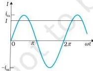
Read Fig 7.3 this way: the curve swings up to \( i_m \) at its highest point, but the rms value \( I = i_m/\sqrt{2} \) is the current that would do the same heating as a steady dc current of \( I \) amperes (p. 180).
Step 1: A 60 W bulb is rated for 220 V.
Find its resistance from \( R = V^2/P \).
\[ R = \frac{(220\ \text{V})^2}{60\ \text{W}} = \frac{48400}{60} \approx 807\ \Omega \]
Step 2: The rms current drawn is \( I = P/V \).
\[ I = \frac{60\ \text{W}}{220\ \text{V}} \approx 0.27\ \text{A} \]
Step 3: The peak mains voltage is \( v_m = \sqrt{2}\,V \).
\[ v_m = 1.414 \times 220 \approx 311\ \text{V} \]
Answer: Resistance \( \approx 807\ \Omega \); rms current \( \approx 0.27\ \text{A} \); peak voltage \( = 311\ \text{V} \).
Resistor: Voltage and Current in Phase
The resistor is the baseline case. With no coil or capacitor to store energy, Ohm’s law keeps its dc form and nothing shifts in time.
Applying Kirchhoff’s loop rule gives \( i = i_m \sin \omega t \) with \( i_m = v_m/R \) — exactly Ohm’s law (NCERT, p. 178).
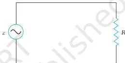
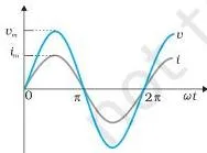
Figures 7.1 and 7.2 show the circuit and the waveform. Notice that \( v \) and \( i \) hit zero, their minima and their maxima at the same instants — that is what in phase means (p. 178).
The subtle point follows: the average current over a cycle is zero, but the average power is not, because \( i^2R \) is always positive (p. 179). Average power is \( \frac{1}{2} i_m^2 R = I^2 R \).
Inductor: Current Lags Voltage by a Quarter Cycle
An inductor opposes changes in current, not the current itself. That single fact is why its current arrives a quarter cycle after the voltage.
The self-induced emf \( L\,di/dt \) opposes the change driven by the source, and integrating the loop equation gives (NCERT, p. 182):
\[ i = i_m \sin\left(\omega t – \frac{\pi}{2}\right), \quad \text{with} \quad X_L = \omega L, \quad i_m = \frac{v_m}{X_L} \]
\( X_L \) is the inductive reactance, measured in ohm. It limits current like a resistance, but it grows with frequency because \( X_L = \omega L \) (p. 182). The minus \( \pi/2 \) means the current lags the voltage by a quarter cycle (p. 182). The constant of integration is zero because the source drives current symmetrically about zero.
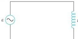

Fig 7.5 shows the circuit — a source connected directly across the inductor — and Fig 7.6 shows the phasors with the current arrow \( \pi/2 \) behind the voltage arrow, and the sine curves shifted by one-quarter period.
Surprising result: the average power over a complete cycle is zero (p. 183). The inductor alternately borrows and returns energy; nothing is consumed.
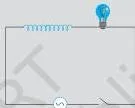
The bulb-and-coil circuit in Fig 7.9 makes reactance concrete. When an iron rod is pushed into the coil, inductance \( L \) rises, so \( X_L \) rises, a larger share of the voltage drops across the coil, and the bulb dims (Example 7.5, p. 186).
Capacitor: Current Leads Voltage by a Quarter Cycle
The capacitor is the mirror image of the inductor: it opposes a steady voltage but passes a changing one, so its current arrives a quarter cycle before the voltage.
With \( v = q/C \) and \( i = dq/dt \), differentiating gives (NCERT, p. 184):
\[ i = i_m \sin\left(\omega t + \frac{\pi}{2}\right), \quad X_C = \frac{1}{\omega C}, \quad i_m = \frac{v_m}{X_C} \]
The plus \( \pi/2 \) means the current leads the voltage by a quarter cycle (p. 185). \( X_C \) is the capacitive reactance (ohm), inversely proportional to both frequency and capacitance — the exact opposite of the inductor (p. 185).
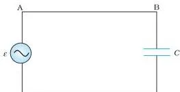
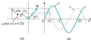
Fig 7.7 shows the circuit and Fig 7.8 the phasor and time graphs: the current arrow sits \( \pi/2 \) ahead of the voltage arrow.
Why does current lead? As the source reverses each half cycle, the capacitor charges and discharges, so current keeps flowing. Current is largest when the voltage passes through zero, because that is when charge is moving fastest between the plates.
With dc the story differs: the capacitor charges once and then blocks current, so a lamp in series with a capacitor glows with ac but not with dc (Example 7.3, p. 185). As with the inductor, the average power over a cycle is zero (p. 185).
Frequency check with original numbers: for \( C = 20\ \mu\text{F} \) at 50 Hz, \( X_C = 1/(2\pi\nu C) \approx 159\ \Omega \). Double the frequency to 100 Hz and \( X_C \) halves to about \( 79.6\ \Omega \), so the same voltage drives twice the current — the halving the chapter’s Example 7.4 notes.
Series LCR Circuit: Impedance and Phase Angle
When R, L and C are in series, the same current flows through all three, but the voltages across them are not in step. This is where the phasor idea earns its keep.
The current is common: \( i = i_m \sin(\omega t + \phi) \). The resistor voltage is in phase with the current, the capacitor voltage lags by \( \pi/2 \), and the inductor voltage leads by \( \pi/2 \) (NCERT, p. 187). Adding these as phasors gives:
\[ Z = \sqrt{R^2 + (X_C – X_L)^2}, \qquad \tan \phi = \frac{X_C – X_L}{R} \]
\( Z \) is the impedance, the total opposition of the whole circuit, in ohm (p. 187). \( \phi \) is the phase angle between the source voltage and the current (p. 188).
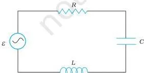
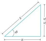
Fig 7.10 shows the three elements in series with the source. Fig 7.12 is the impedance diagram: a right-angled triangle with \( Z \) as the hypotenuse, \( R \) on one side and \( X_C – X_L \) on the other (p. 188).
Sign of \( \phi \): if \( X_C \gt X_L \) the circuit is predominantly capacitive and the current leads the voltage; if \( X_C \lt X_L \) it is predominantly inductive and the current lags (p. 188).
Why voltages do not add arithmetically: in Example 7.6, a 200 ohm resistor and \( 15.0\ \mu\text{F} \) capacitor on 220 V give \( V_R = 151 \) V and \( V_C = 160.3 \) V, whose ordinary sum 311.3 V beats the 220 V source. The paradox dissolves because the two voltages are \( \pi/2 \) out of phase — they combine by Pythagoras: \( \sqrt{151^2 + 160.3^2} = 220 \) V (p. 190).
Step 1: An RC series circuit has \( R = 100\ \Omega \) and \( C = 20\ \mu\text{F} \) on a 50 Hz supply.
Find \( X_C \).
\[ X_C = \frac{1}{2\pi\nu C} = \frac{1}{2\pi(50)(20 \times 10^{-6})} \approx 159\ \Omega \]
Step 2: Combine \( R \) and \( X_C \) by Pythagoras to get \( Z \).
\[ Z = \sqrt{R^2 + X_C^2} = \sqrt{100^2 + 159^2} \approx 188\ \Omega \]
Answer: \( X_C \approx 159\ \Omega \) and \( Z \approx 188\ \Omega \). A plain sum \( R + X_C = 259\ \Omega \) would be wrong — the two oppositions act at right angles, not in line.
Resonance in the Series LCR Circuit
Some systems oscillate naturally at one frequency; drive them at that same frequency and the response becomes large. The series LCR circuit does exactly this — which is how a radio picks one station out of many.
The chapter compares it to a child on a swing, where pulls timed to the swing’s natural frequency build up large swings (NCERT, p. 188). In the circuit, the frequency-dependent terms cancel when:
\[ \omega_0 = \frac{1}{\sqrt{LC}} \]
At this frequency \( X_C = X_L \), the impedance falls to \( Z = R \), and the current amplitude is maximum: \( i_m = v_m/R \) (p. 189).
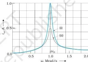
The resonance curve above plots \( i_m \) against \( \omega \) for two resistances. The current peaks at the resonant frequency \( \omega_0 \), and the smaller \( R \) is, the sharper and higher the peak (p. 189).
Both L and C are required. Resonance happens only because the voltages across L and C cancel; a pure RL or RC circuit has no such cancellation, so resonance is impossible there (p. 189).
Applications: tuning a radio to a station by varying the capacitance until the circuit resonates at the station’s frequency (p. 189), and the airport metal detector, where metal in a pocket shifts the resonance and changes the current (Example 7.10, p. 193).
Step 1: Find the resonant angular frequency for \( L = 40\ \text{mH} \) and \( C = 100\ \mu\text{F} \).
\[ \omega_0 = \frac{1}{\sqrt{LC}} = \frac{1}{\sqrt{(0.040)(100 \times 10^{-6})}} = \frac{1}{2.0 \times 10^{-3}} = 500\ \text{rad/s} \]
Step 2: Convert to hertz: \( f_0 = \omega_0/2\pi \).
\[ f_0 = \frac{500}{2\pi} \approx 79.6\ \text{Hz} \]
Answer: \( \omega_0 = 500\ \text{rad/s} \), about 79.6 Hz.
Power in AC Circuits: Power Factor and Wattless Current
In an LCR circuit the current and voltage are out of step, so the product \( vi \) partly stores and returns energy instead of dissipating it. The power factor tells you how much of the current actually does work.
Averaging \( p = vi \) over a cycle, the oscillating term \( \cos(2\omega t + \phi) \) averages to zero and only the constant term survives (NCERT, p. 191):
\[ P = VI \cos \phi \]
\( \cos \phi \) is the power factor (p. 191). The chapter gives four cases:
- Pure resistor: \( \phi = 0 \), \( \cos \phi = 1 \), maximum power dissipation.
- Pure inductor or capacitor: \( \phi = \pm\pi/2 \), \( \cos \phi = 0 \), no power dissipated although current flows — the wattless current (p. 191).
- LCR circuit: power is dissipated only in the resistor (p. 191).
- At resonance: \( X_C = X_L \), \( \phi = 0 \), \( \cos \phi = 1 \), maximum power (p. 191).
Why a poor power factor costs money: to deliver a fixed power \( P = VI \cos \phi \) at a fixed voltage, a small \( \cos \phi \) forces a larger current, and the transmission lines lose \( I^2R \) as heat (Example 7.7, p. 191).
The fix is a capacitor in parallel that draws an equal leading wattless current to cancel the lagging one, raising \( \cos \phi \) toward 1 (p. 192).
Transformers: Stepping Voltage Up and Down
A transformer changes the voltage level of ac using mutual induction — the reason ac, not dc, is used for power transmission.
An alternating current in the primary creates an alternating flux that links the secondary and induces an emf there (NCERT, p. 194).
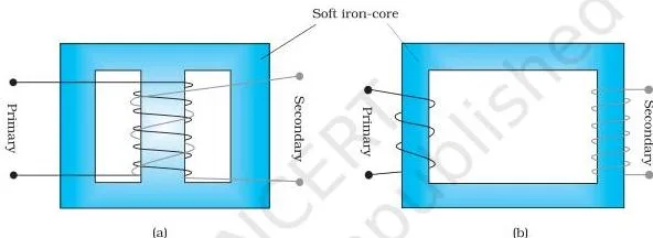
Fig 7.16 shows the two standard windings: both coils on a soft-iron core, either wound one on top of the other or on separate limbs (p. 194). The core ensures nearly all the flux links both coils.
The turn-ratio relations are (p. 195):
\[ \frac{V_s}{V_p} = \frac{N_s}{N_p} \qquad \text{and} \qquad \frac{I_s}{I_p} = \frac{N_p}{N_s} \]
If \( N_s \gt N_p \), voltage is stepped up and current down — a step-up transformer; the reverse is a step-down transformer (p. 195). These relations assume an ideal transformer: the primary resistance and current are small, almost all flux links both coils, and the secondary current is small (p. 195).
Step 1: A transformer has 200 primary turns and 40 secondary turns, fed at 220 V.
Find the secondary voltage.
\[ V_s = \frac{N_s}{N_p}V_p = \frac{40}{200} \times 220 = 44\ \text{V} \]
Step 2: If the secondary supplies 2 A, find the primary current from \( I_p = (N_s/N_p)I_s \).
\[ I_p = \frac{40}{200} \times 2 = 0.4\ \text{A} \]
Answer: \( V_s = 44\ \text{V} \) and \( I_p = 0.4\ \text{A} \). Energy check: \( 220 \times 0.4 = 88\ \text{W} \) in, and \( 44 \times 2 = 88\ \text{W} \) out.
Energy losses in real transformers (pp. 195-196): flux leakage, resistance of the windings (\( I^2R \)), eddy currents in the core (reduced by laminating it), and hysteresis in the core material.
Why this matters for transmission: the generator voltage is stepped up so the current falls and the \( I^2R \) line loss drops, then stepped down at sub-stations near consumers (p. 196). A step-up transformer does not create energy — the current falls in the same proportion (POINTS TO PONDER, p. 199).
Figure Walkthrough: How to Read a Phasor Diagram
Phasor diagrams look abstract, but they are just rotating arrows whose shadow on the vertical axis is the instantaneous value of the voltage or current.
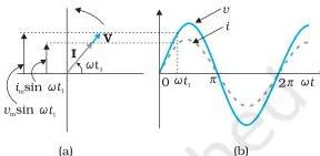
In Fig 7.4, the arrows V and I rotate together at angular speed \( \omega \). Their vertical projections \( v_m \sin \omega t \) and \( i_m \sin \omega t \) trace out the sine curves beside them. For a resistor the two arrows point the same way at every instant, so the phase angle is zero (NCERT, p. 181).
Important caution: voltage and current are scalars, not vectors. Phasors are only a convenient way of adding harmonically varying scalars using the vector rule (footnote, p. 181; POINTS TO PONDER, p. 199).
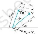
Fig 7.11 is the construction that solves the LCR circuit. Draw the current phasor I; put \( \mathbf{V}_R \) parallel to it, \( \mathbf{V}_C \) a quarter turn behind, and \( \mathbf{V}_L \) a quarter turn ahead. The source voltage \( \mathbf{V} \) is the phasor sum.
Because \( \mathbf{V}_L \) and \( \mathbf{V}_C \) lie on the same line pointing opposite ways, they subtract before combining with \( \mathbf{V}_R \) by Pythagoras (p. 187).
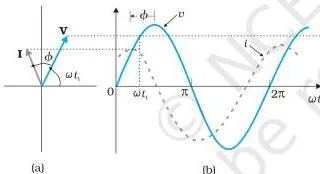
Fig 7.13 shows the case \( X_C \gt X_L \): the current arrow sits ahead of the voltage arrow, and the angle between \( \mathbf{V}_R \) and \( \mathbf{V} \) is the phase angle \( \phi \) (p. 188).
Key Definitions from the Chapter
These are the named quantities the chapter defines. Each entry gives the plain meaning and the page where NCERT defines it.
| Term | Plain-language meaning | NCERT page |
|---|---|---|
| Alternating voltage / current | A voltage or current that varies sinusoidally with time, reversing direction every half cycle. | p. 176 |
| Amplitude \( v_m \) | The maximum value the oscillating voltage reaches on either side of zero. | p. 178 |
| Angular frequency \( \omega \) | The rate of oscillation of the sine wave, related to ordinary frequency by \( \omega = 2\pi\nu \). | p. 178 |
| rms current \( I \) | The steady dc current that produces the same average Joule heating; \( I = i_m/\sqrt{2} \). | p. 180 |
| rms voltage \( V \) | The equivalent dc voltage for the same average power; \( V = v_m/\sqrt{2} \). | p. 180 |
| Phasor | A rotating arrow whose vertical projection gives the instantaneous value of a sinusoidally varying quantity; a representation, not a real vector. | p. 181 |
| Inductive reactance \( X_L \) | Opposition of an inductor to ac current; \( X_L = \omega L \), measured in ohm. | p. 182 |
| Capacitive reactance \( X_C \) | Opposition of a capacitor to ac current; \( X_C = 1/\omega C \), measured in ohm. | p. 184 |
| Impedance \( Z \) | Total opposition of an ac circuit; for series LCR, \( Z = \sqrt{R^2 + (X_C – X_L)^2} \). | p. 187 |
| Resonant frequency \( \omega_0 \) | The frequency at which \( X_C = X_L \) and current is maximum; \( \omega_0 = 1/\sqrt{LC} \). | p. 189 |
| Power factor \( \cos \phi \) | The cosine of the phase angle between voltage and current; it scales average power in \( P = VI\cos\phi \). | p. 191 |
| Wattless current | Current that flows in a purely inductive or capacitive circuit yet dissipates no average power, because \( \cos\phi = 0 \). | p. 191 |
| Step-up / step-down transformer | A device using mutual induction to raise (\( N_s \gt N_p \)) or lower (\( N_s \lt N_p \)) an ac voltage. | p. 195 |
The chapter’s own physical quantities table on p. 198 collects these with their dimensions, units and definitions in one place.
Alternating Current Formulas: Symbols, Units and When to Use Them
One compact sheet of the formulas that matter most, with symbol meanings and units, so you can check a formula without re-reading the chapter.
| Formula | What each symbol means | Unit | Where it applies |
|---|---|---|---|
| \( v = v_m \sin \omega t \) | \( v \) instantaneous voltage; \( v_m \) amplitude; \( \omega \) angular frequency | V for \( v, v_m \); rad/s for \( \omega \) | Any ac source |
| \( i_m = v_m/R \) | \( i_m \) peak current; \( R \) resistance | A; ohm | Pure resistor |
| \( I = i_m/\sqrt{2} \) | \( I \) rms current | A | Any sinusoidal current |
| \( V = v_m/\sqrt{2} \) | \( V \) rms voltage | V | Any sinusoidal voltage |
| \( P = I^2 R \) | \( P \) average power over a cycle | W | Pure resistor |
| \( X_L = \omega L \) | \( X_L \) inductive reactance; \( L \) inductance | ohm | Pure inductor |
| \( i_m = v_m/X_L \) | peak current | A | Pure inductor |
| \( X_C = 1/\omega C \) | \( X_C \) capacitive reactance; \( C \) capacitance | ohm | Pure capacitor |
| \( i_m = v_m/X_C \) | peak current | A | Pure capacitor |
| \( Z = \sqrt{R^2 + (X_C – X_L)^2} \) | \( Z \) impedance of the whole circuit | ohm | Series LCR |
| \( \tan \phi = (X_C – X_L)/R \) | \( \phi \) phase angle between source voltage and current | dimensionless | Series LCR |
| \( \omega_0 = 1/\sqrt{LC} \) | \( \omega_0 \) resonant angular frequency | rad/s (Hz if divided by \( 2\pi \)) | Series LCR with both L and C |
| \( P = VI\cos\phi \) | average power; \( \cos\phi \) power factor | W | Any ac circuit |
| \( V_s/V_p = N_s/N_p \) | secondary and primary voltage and turn counts | V | Ideal transformer |
| \( I_s/I_p = N_p/N_s \) | secondary and primary current, inverse ratio | A | Ideal transformer |
Common Mistakes Students Make in Alternating Current
These are the places where the chapter itself warns readers — several come straight from its POINTS TO PONDER.
| Mistake | Correct rule | How to check your answer |
|---|---|---|
| Treating 220 V mains as the peak voltage | Stated ac voltages are rms; the peak is \( v_m = \sqrt{2}\,V \approx 311 \) V (p. 180; POINTS, p. 198). | Multiply any stated mains voltage by 1.414 — if an answer treats 220 V as the peak, it is wrong. |
| Adding out-of-phase voltages arithmetically | \( V_R \) and \( V_C \) are \( \pi/2 \) apart and combine by Pythagoras (Example 7.6, p. 190; POINTS, p. 199). | The phasor sum must equal the source voltage; a plain sum larger than the source is your signal. |
| Concluding zero average current means zero power | Power follows \( i^2 \), which is positive in both half-cycles (p. 179). | Write \( p = i^2R \) — it is never negative over the cycle. |
| Swapping lead and lag | Inductor current lags by \( \pi/2 \); capacitor current leads by \( \pi/2 \) (pp. 182-185). | Read the sign in the current equation: \( \omega t – \pi/2 \) lags, \( \omega t + \pi/2 \) leads. |
| Expecting resonance in an RL or RC circuit | Resonance needs both L and C so their voltages can cancel (p. 189; POINTS, p. 199). | If \( X_L \) or \( X_C \) is missing from the impedance, no frequency brings it down to \( R \). |
| Treating phasors as real vectors | Phasors represent scalar quantities; they merely combine like vectors (footnote, p. 181; POINTS, p. 199). | Remember voltage and current are scalars — the arrow is a bookkeeping device. |
| Writing \( P = VI \) for every ac circuit | The full form is \( P = VI\cos\phi \); \( P = VI \) holds only when \( \cos\phi = 1 \) (p. 191). | For a pure inductor or capacitor the average power must come out zero. |
| Thinking a step-up transformer creates energy | Voltage goes up, current falls in the same proportion; power in equals power out (POINTS, p. 199). | Check \( V_p I_p = V_s I_s \) in any ideal transformer calculation. |
Working Through the Exercises: What Each Question Tests
The exercise set at the end of the chapter (p. 200) is mapped below to the idea each question tests, so you can practise in a targeted order. Exercise 7.8 names Fig 7.17, shown here.
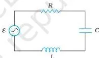
Fig 7.17 belongs to Exercise 7.8: a 230 V variable-frequency source drives \( L = 5.0 \) H, \( C = 80\ \mu\text{F} \) and \( R = 40\ \Omega \) in series. The question asks for the resonance frequency, the impedance and current amplitude at resonance, and the individual rms drops across the three elements.
| Exercise | What it tests | Straight to it |
|---|---|---|
| 7.1 and 7.2 | rms and peak conversions, net power in a resistor | \( I = V/R \), \( P = I^2R \), \( v_m = \sqrt{2}\,V \) |
| 7.3 and 7.4 | reactance and rms current in a pure inductor and a pure capacitor | \( X_L = 2\pi\nu L \), \( X_C = 1/(2\pi\nu C) \), then \( I = V/X \) |
| 7.5 | why net power is zero in those two circuits | \( \cos\phi = 0 \); energy is stored and returned, not dissipated |
| 7.6 | angular frequency of free LC oscillations | \( \omega_0 = 1/\sqrt{LC} \) |
| 7.7 | average power at the natural frequency | At resonance \( Z = R \), so \( P = V^2/R \) |
| 7.8 | the full resonance workout with Fig 7.17 | \( \omega_0 \) from L and C; \( Z = R \), \( i_m = v_m/R \); then rms drops and \( V_L – V_C = 0 \) |
A complete answer to 7.8 must state the source frequency from \( \omega_0 = 1/\sqrt{LC} \), give the impedance \( Z = R = 40\ \Omega \) and the current amplitude \( i_m = v_m/R \) at resonance, then the rms drops across R, L and C separately, and close by showing the LC combination’s potential drop is zero because \( V_L \) and \( V_C \) are equal and opposite at resonance.
The worked examples that build the reasoning behind these questions include Example 7.5 (qualitative — iron rod in a coil), Example 7.6 (phasor addition paradox), Example 7.7 (power factor and transmission loss) and Example 7.10 (the airport metal detector).
Textbook contents and the examinable syllabus are not always identical — check the current official syllabus for what is examinable.
The Chapter in Eight Points
The chapter’s own SUMMARY (pp. 196-197) condenses everything into eight results. Here they are restated:
- Resistor: \( v = v_m\sin\omega t \) drives \( i = i_m\sin\omega t \) with \( i_m = v_m/R \); voltage and current are in phase.
- rms values: \( I = i_m/\sqrt{2} = 0.707\,i_m \), \( V = v_m/\sqrt{2} = 0.707\,v_m \), and \( P = IV = I^2R \).
- Inductor: \( i = i_m\sin(\omega t – \pi/2) \), \( X_L = \omega L \); current lags voltage by \( \pi/2 \); average power zero.
- Capacitor: \( i = i_m\sin(\omega t + \pi/2) \), \( X_C = 1/\omega C \); current leads voltage by \( \pi/2 \); average power zero.
- Series LCR: \( i_m = v_m/Z \), \( Z = \sqrt{R^2 + (X_C – X_L)^2} \), \( \tan\phi = (X_C – X_L)/R \), and average power \( P = VI\cos\phi \).
- Wattless current: in a purely inductive or capacitive circuit \( \cos\phi = 0 \), so no power is dissipated even though current flows.
- Phasors: rotating arrows whose magnitude is the amplitude; phasor diagrams make the phase relations visible.
- Transformers: \( V_s = (N_s/N_p)V_p \) and \( I_s = (N_p/N_s)I_p \); more secondary turns step voltage up, fewer step it down.
For the subtleties behind these points — the 240 V to 340 V peak, why voltages add by Pythagoras, and why a step-up transformer conserves energy — read POINTS TO PONDER on p. 198.
Related Resources
Continue with the rest of Class 12 Physics from these pages:
- Class 12 Physics notes — chapter-wise notes for the book
- Class 12 notes hub — other Class 12 subjects
- CBSE notes home — notes across classes and subjects
- Previous chapter: Electromagnetic Induction — the transformer in section 7.8 builds on its mutual induction and Lenz’s law
- Next chapter: electromagnetic waves
- Later in the book, semiconductor electronics shows how diodes convert ac to dc by rectification
For official sources: the chapter file is the Alternating Current Class 12 NCERT Chapter 7 PDF, and the official NCERT site hosts all current textbook editions. The edition this page follows is the NCERT Physics Part I textbook for Class 12; NCERT settles textbook editions and official PDFs, while CBSE settles the curriculum, syllabus and examinations.
Sources and Data Verification
The page numbers, figure captions, formulas and exercise texts used here come from the NCERT Physics Part I textbook for Class 12, Chapter 7 (Alternating Current), official edition published at ncert.nic.in.
This page covers only Chapter 7 of Physics Part I. It does not cover the other chapters of the book or other subjects. The NCERT information on this page is maintained for the current editions published at ncert.nic.in.
NCERT settles textbook editions and official PDFs; CBSE settles the curriculum, syllabus and examinations.
Frequently Asked Questions
Why is 220 V called the rms value of the mains supply and what is its peak value?
220 V is the rms value, the value usually quoted for ac voltage. The sine wave’s average over a cycle is zero, so the useful measure is the effective heating value; the peak is \( v_m = \sqrt{2} \times 220 \approx 311 \) V (p. 180). An outlet labelled 240 V has a 340 V peak (POINTS TO PONDER, p. 198).
Why does current lag voltage in an inductor but lead voltage in a capacitor?
An inductor’s self-induced emf opposes any change in current, so the current finishes changing a quarter cycle after the voltage — it lags by \( \pi/2 \) (p. 182). A capacitor charges and discharges as the source reverses, so current is largest when the voltage passes through zero — it leads by \( \pi/2 \) (p. 185).
What is the difference between reactance and impedance?
Reactance is the frequency-dependent opposition of a single element: \( X_L = \omega L \) for an inductor and \( X_C = 1/\omega C \) for a capacitor (pp. 182, 184). Impedance is the total opposition of the whole circuit: \( Z = \sqrt{R^2 + (X_C – X_L)^2} \) for a series LCR circuit (p. 187). Both are measured in ohm.
Why is the average power consumed by a pure inductor or a pure capacitor zero?
Because the instantaneous power \( p = vi \) contains a \( \sin(2\omega t) \) term whose average over a complete cycle is zero (pp. 183, 185). Energy is stored during part of the cycle and returned during the rest, so nothing is dissipated. The power factor \( \cos\phi \) is zero in both cases (p. 191).
What is resonance in a series LCR circuit and at what frequency does it occur?
Resonance is the condition \( X_C = X_L \), at which the two reactances cancel, the impedance falls to \( R \), and the current is maximum (p. 189). It occurs at \( \omega_0 = 1/\sqrt{LC} \) and requires both L and C to be present — there is no resonance in an RL or RC circuit alone (p. 189).
Which exercises in this chapter test resonance?
Exercises 7.6, 7.7 and 7.8. Exercise 7.6 asks for the angular frequency of free LC oscillations, \( \omega_0 = 1/\sqrt{LC} \); 7.7 gives the average power at the natural frequency; and 7.8 is the full resonance workout using Fig 7.17 — resonance frequency, impedance, current amplitude, and the zero potential drop across the LC combination (p. 200).
Reference: NCERT Class 12 Physics textbook, chapter 7, official edition on ncert.nic.in.
Explore Class 12 Physics Books
Class 12 Physics on LearnCBSE:
Related chapters: