
This page is built around the ray optics and optical instruments class 12 NCERT chapter — Chapter 9 of the NCERT Physics Part II textbook, the first chapter of Part II, printed on pages 220–253 of the 2026-27 reprint.
The official chapter PDF is right here; beneath it is a section-by-section map, the sign convention with the mirror and lens equations, worked numbers you have not seen in class, and the mistakes students make in this chapter.
Download Ray Optics and Optical Instruments Class 12 chapter PDF
NCERT publishes the official file free on its own website: open the Ray Optics and Optical Instruments Class 12 NCERT chapter PDF to read the chapter exactly as printed — every figure, derivation and exercise — or keep it open alongside this page as a reading guide.
| What the chapter holds | Count | Where it is used |
|---|---|---|
| Printed pages | 34 | |
| Sections in the chapter | 17 | |
| Figures with NCERT captions | 29 | |
| Tables | 1 | |
| Worked examples | 6 | solved step by step in our NCERT Solutions |
| Exercise questions | 31 | answered in our NCERT Solutions |
| Official NCERT PDF | Download the chapter PDF | the chapter exactly as NCERT publishes it |
Chapter at a glance: what is inside this chapter
The table below collects what the chapter holds — its sections, figures, worked examples and exercise questions — so you can see the size of the chapter before you start. The section map after it tells you where each topic begins.
What this chapter covers, section by section
Use this as an index. Every printed section is listed with the page on which it starts in the book.
- 9.1 Introduction — why light can be treated as rays; the speed of light (p. 220)
- 9.2 Reflection of light by spherical mirrors — sign convention, focal length, the mirror equation (p. 222)
- 9.3 Refraction — Snell’s law, lateral shift, apparent depth (p. 228)
- 9.4 Total internal reflection — critical angle, prisms, optical fibres (p. 229)
- 9.5 Refraction at spherical surfaces and by lenses — one-surface formula, lens maker’s formula, thin lens formula, power, combinations (p. 232)
- 9.6 Refraction through a prism — prism relations and minimum deviation (p. 239)
- 9.7 Optical instruments — simple and compound microscope, telescope, reflecting telescopes (p. 240)
- Summary, Points to Ponder and Exercises — the chapter’s own revision material (p. 246–253)
Core ideas in Ray Optics and Optical Instruments
Before any formula: why treat light as rays at all? The book’s Chapter 8 treats light as an electromagnetic wave of wavelength roughly 400–750 nm. That wavelength is far smaller than everyday objects around you, so over ordinary distances a wave can be taken to travel along a straight line — a ray joined to another ray, a beam (NCERT p. 220–221).
This chapter then uses the two basic laws — equal angles in reflection and Snell’s law in refraction — to explain how mirrors, lenses, prisms and instruments form images.
The Cartesian sign convention
This convention decides the sign of every distance you substitute, so it comes first. All distances are measured from the pole of a mirror or the optical centre of a lens. Distances measured in the direction of the incident light are positive; distances measured against it are negative. Heights measured upwards are positive, downwards negative (Fig. 9.2, NCERT p. 222).
The payoff is that one mirror equation and one lens formula handle every case — concave or convex, real or virtual. The rule you will use most: the object sits on the side the light comes from, so u is always negative, and a concave mirror’s focus lies on that same side, so f is negative for a concave mirror.
The full walkthrough of Fig. 9.2 is in the figure section below.
Mirror equation and magnification
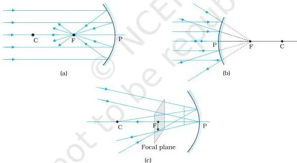
Two terms first. An image is real if the reflected rays actually meet at the image point; it is virtual if the rays only appear to diverge from the point when produced backwards (NCERT p. 224). For ray diagrams you need any two of four convenient rays (NCERT p. 224):
- A ray parallel to the principal axis reflects through the focus.
- A ray through (or directed toward) the centre of curvature retraces its path.
- A ray through (or directed toward) the focus reflects parallel to the principal axis.
- A ray striking the pole reflects obeying the laws of reflection.
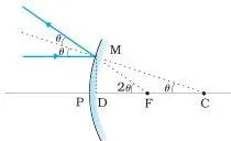
For rays close to the pole (paraxial rays), the geometry gives \( f = R/2 \) for a mirror (NCERT p. 224). Comparing similar triangles and applying the sign convention gives the mirror equation \( \frac{1}{v} + \frac{1}{u} = \frac{1}{f} \) (NCERT p. 225) and the linear magnification \( m = \frac{h’}{h} = -\frac{v}{u} \) (NCERT p. 226). A negative m means a real, inverted image.
Worked example (original numbers). A concave mirror has radius of curvature 24 cm; an object stands 18 cm from the pole.
Step 1 — signs: \( f = R/2 = 12\ \text{cm} \), but the concave mirror’s focus is on the incoming-light side, so \( f = -12\ \text{cm} \).
The object is 18 cm in front of the pole, also against the incident light, so \( u = -18\ \text{cm} \).
Step 2 — mirror equation: \( \frac{1}{v} + \frac{1}{u} = \frac{1}{f} \), so \[ \frac{1}{v} = \frac{1}{f} – \frac{1}{u} = \frac{1}{-12} – \frac{1}{-18} = -\frac{1}{12} + \frac{1}{18} = -\frac{1}{36} \]
Step 3 — interpret v: \( v = -36\ \text{cm} \).
A negative v for a mirror means the image is on the same side as the object — in front of the mirror — so it is real.
Step 4 — magnification: \( m = -v/u = -(-36)/(-18) = -2 \).
Negative m means inverted; magnitude 2 means magnified twice.
Final answer: image at \( v = -36\ \text{cm} \) (36 cm in front of the mirror), real, inverted, magnified 2×.
Refraction, Snell’s law and apparent depth
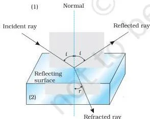
Refraction is the change in direction of a ray when it enters another transparent medium (NCERT p. 228). Snell’s law states that \( \frac{\sin i}{\sin r} = n_{21} \), where \( n_{21} \) is the refractive index of the second medium with respect to the first.
It is a characteristic of the pair of media and depends on the wavelength of light, but it is independent of the angle of incidence. If \( r \lt i \), the ray bends toward the normal and medium 2 is said to be optically denser.
The chapter warns against one confusion: optical density is not mass density. Turpentine has a lower mass density than water but a higher optical density (NCERT p. 228).
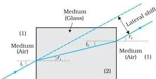
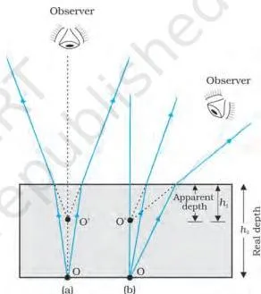
Two everyday effects follow from refraction: a ray through a parallel-sided glass slab emerges parallel to itself but shifted sideways (lateral shift, Fig. 9.9), and a water tank’s bottom looks raised — apparent depth = real depth / refractive index for near-normal viewing (Fig. 9.10, NCERT p. 229).
Total internal reflection and the critical angle
A ray going from an optically denser to a rarer medium bends away from the normal, so the refracted angle grows faster than the incident angle. At one incident angle the refracted ray grazes the surface at \( 90^\circ \) — that angle is the critical angle \( i_c \).
Beyond it, refraction is impossible and the whole ray reflects back into the denser medium: total internal reflection (NCERT p. 229–230).
Two conditions must both hold: light must travel from denser to rarer, and the angle of incidence must exceed \( i_c \), where \( \sin i_c = n_{21} \). The book’s Table 9.1 lists critical angles with respect to air: water \( 48.75^\circ \), crown glass \( 41.14^\circ \), dense flint glass \( 37.31^\circ \), diamond \( 24.41^\circ \).
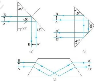
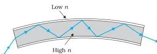
Total internal reflection explains prisms that bend light by \( 90^\circ \) or \( 180^\circ \) (the prism’s critical angle must be below \( 45^\circ \), which holds for crown and dense flint glass), and optical fibres, where a core of higher refractive index traps light by repeated total internal reflection — over 95% of light survives one kilometre of silica fibre (NCERT p. 231–232).
Diamond’s sparkle and mirages are the same phenomenon. You can watch it yourself with a laser pointer and slightly turbid water: the beam glows inside the water, and beyond the critical angle the refracted spot disappears completely (NCERT p. 230).
Refraction at a spherical surface and thin lenses
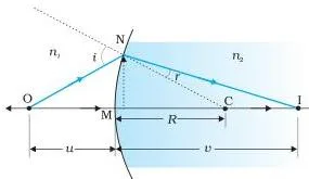
One curved surface first. For a spherical surface of radius R separating media of refractive index \( n_1 \) and \( n_2 \), the relation is (NCERT p. 233):
\[ \frac{n_2}{v} – \frac{n_1}{u} = \frac{n_2 – n_1}{R} \]
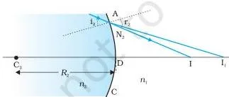
A thin lens is two such surfaces back to back. Applying the one-surface formula twice gives the lens maker’s formula (NCERT p. 234) — the design formula that fixes a lens’s focal length from its radii and glass:
\[ \frac{1}{f} = (n_{21} – 1)\left( \frac{1}{R_1} – \frac{1}{R_2} \right) \]
The same derivation closes with the thin lens formula (NCERT p. 235) — the use formula that links object and image distances:
\[ \frac{1}{v} – \frac{1}{u} = \frac{1}{f} \]
For a lens the magnification is \( m = \frac{h’}{h} = \frac{v}{u} \) — note the sign difference from the mirror formula (NCERT p. 235).
Worked example (original numbers). A double convex lens in air has refractive index 1.5 and radii of curvature 20 cm and −25 cm.
Step 1 — signs: Light enters the first surface, whose centre of curvature lies on the far side, so \( R_1 = +20\ \text{cm} \).
The second surface has its centre on the incident side, so \( R_2 = -25\ \text{cm} \).
In air, \( n_{21} = 1.5 \).
Step 2 — lens maker’s formula:
\[ \frac{1}{f} = (1.5 – 1)\left( \frac{1}{20} – \frac{1}{-25} \right) = 0.5\left( \frac{1}{20} + \frac{1}{25} \right) \]
\[ = 0.5 \times 0.09\ \text{cm}^{-1} = 0.045\ \text{cm}^{-1} \]
Step 3 — focal length and power: \( f = 1/0.045 \approx 22.2\ \text{cm} \).
Power needs f in metres: \( f \approx 0.222\ \text{m} \), so \( P = 1/f \approx 4.5\ \text{D} \).
Final answer: \( f \approx +22.2\ \text{cm} \), \( P \approx +4.5\ \text{D} \); positive power means a converging lens.
The chapter’s Example 9.6 makes the same formula dramatic: a glass lens of \( n = 1.47 \) disappears when dipped into a liquid of the same refractive index, because the lens maker’s formula then gives \( 1/f = 0 \), so \( f \to \infty \) and the lens behaves like a plane sheet of glass (NCERT p. 236).
Power of a lens and combinations
Power measures how strongly a lens converges or diverges light: \( P = 1/f \) with f in metres. Its SI unit is the dioptre, \( 1\ \text{D} = 1\ \text{m}^{-1} \).
Convex lenses have positive power, concave lenses negative power — an optician’s \( +2.5\ \text{D} \) lens is a convex lens of focal length \( +40\ \text{cm} \), and \( -4.0\ \text{D} \) is a concave lens of \( -25\ \text{cm} \) (NCERT p. 236).
Thin lenses placed in contact combine simply. Their focal lengths add inversely, their powers add algebraically, and their magnifications multiply (NCERT p. 237–238):
\[ \frac{1}{f} = \frac{1}{f_1} + \frac{1}{f_2} + \cdots, \qquad P = P_1 + P_2 + \cdots, \qquad m = m_1 m_2 \cdots \]
Work lens by lens from the object side: the image formed by the first lens acts as a virtual object for the second — the step where many students lose the sign. The combination is used in cameras, microscopes and telescopes to get a desired power with sharper images.
Refraction through a prism
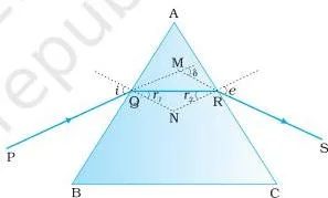
A prism adds two refractions. The geometry of Fig. 9.21 gives \( r_1 + r_2 = A \) and \( \delta = i + e – A \) (NCERT p. 239), where \( \delta \) is the angle of deviation between the incident and emergent rays.
Deviation depends on the angle of incidence, and the \( \delta \) versus \( i \) curve has a minimum \( D_m \) at which the path through the prism is symmetric: \( i = e \) and \( r_1 = r_2 = A/2 \). That symmetry gives the refractive index of the prism (NCERT p. 240):
\[ n_{21} = \frac{\sin\left(\frac{A + D_m}{2}\right)}{\sin\left(\frac{A}{2}\right)} \]
For a thin prism, \( D_m = (n_{21} – 1)A \). Worked example (original numbers): a prism of angle \( 6^\circ \) and refractive index 1.5.
Step 1: The prism angle is small, so the thin-prism formula applies: \( D_m = (n_{21} – 1)A \).
Step 2 — substitute: \( n_{21} = 1.5 \), \( A = 6^\circ \):
\[ D_m = (1.5 – 1) \times 6^\circ = 0.5 \times 6^\circ = 3^\circ \]
Final answer: \( D_m = 3^\circ \). A thin prism of angle \( 6^\circ \) and refractive index 1.5 deviates light by \( 3^\circ \).
Microscopes and telescopes
The instrument section applies the same lens rules to the human eye, using the near point \( D \approx 25\ \text{cm} \) as the benchmark. A simple microscope is a single convex lens of small focal length: \( m = 1 + D/f \) when the image is at the near point, and \( m = D/f \) when the image is at infinity (NCERT p. 242).
A lens of \( f = 5\ \text{cm} \) gives a magnification of six.
The chapter is careful to separate linear magnification from angular magnification (magnifying power). Linear magnification compares sizes, \( m = h’/h \); magnifying power compares the angles the object and image subtend at the eye. For the simple microscope the two give different formulas, \( 1 + D/f \) versus \( D/f \).
The chapter’s Points to Ponder makes the subtle point: object and image subtend the same angle here — the lens still magnifies because it lets you hold a small object far closer than 25 cm, so it subtends a large angle at that short distance (NCERT p. 242, 248).
A compound microscope uses a short-focal-length objective to form a real, inverted, magnified intermediate image, which the eyepiece then magnifies again. For a final image at infinity, its magnifying power is (NCERT p. 243):
\[ m = \left( \frac{L}{f_o} \right) \left( \frac{D}{f_e} \right) \]
where \( L \) is the tube length between the focal points of objective and eyepiece. Small \( f_o \) and \( f_e \) give large magnification — a simple microscope manages at most about 9 times, a compound microscope hundreds.
A telescope does the opposite job: large angular magnification of distant objects. Its magnifying power is \( m = f_o/f_e \), and in normal adjustment the tube length is \( f_o + f_e \) (NCERT p. 244). The objective has a large focal length and aperture; the eyepiece is short.
Refracting telescopes use lenses; reflecting telescopes use a concave mirror objective, which has no chromatic aberration, weighs less, and can be supported over its whole back. The Cassegrain arrangement sends light from a concave primary mirror to a convex secondary and out through a hole in the primary — a long focal length packed into a short tube (NCERT p. 245–246).
Figure walkthrough: how to read the ray diagrams
![(a) shows the geometry of image formation by a double convex lens. The image formation can be seen in terms of two steps: (i) The first refracting surface forms the image $I_1$ of the object O [Fig. 9.16(b)]. The image $I_1$ acts as a virtual object for the second surface that forms the image at I [Fig. 9.16(c)]. Applying Eq. (9.15) to the first interface ABC, we get](https://www.learncbse.net/images/ray-optics-and-optical-instruments-a-shows-the-geometry-of-image-formation-by-a-double-convex-l.webp "Ray Optics and Optical Instruments Class 12: NCERT Physics Part II")
The chapter is carried by its ray diagrams. Each figure below is the one in your book, with the NCERT caption, the page, and what to look at. If a diagram confuses you, the reading tip is the fastest way back on track.
Reading the mirror diagrams
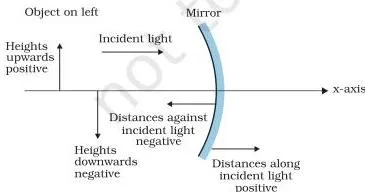
Everything in this chapter hangs on which side of the pole is positive. Fig. 9.2 marks the mirror, its pole and its principal axis, with the distance directions the convention uses: the object side carries the negative direction (against the incident light), the far side positive, and heights above the axis positive.
Reading tip: every time you substitute \( u \), \( v \) or \( f \), ask which side of the pole the point lies on — that decides the sign.
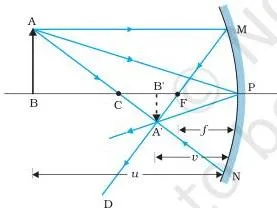
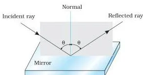
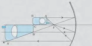
Fig. 9.5 shows three rays from the object tip: the parallel ray (reflects through the focus), the ray through the centre of curvature (retraces its path), and the ray to the pole (reflects symmetrically). All three meet at the image tip — that is what “real” means.
Reading tip: find the ray through the centre of curvature first; it is the easiest to draw and anchors the rest of the diagram.
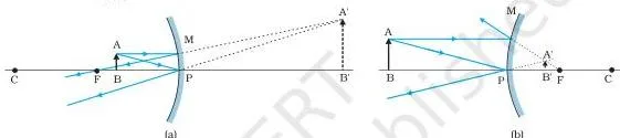
Case (a) shows a concave mirror with the object between the pole and the focus: the reflected rays diverge, so the eye traces them backwards to an erect, virtual image behind the mirror. Case (b) does the same for a convex mirror, which always gives a virtual, erect, diminished image.
Reading tip: whenever the reflected rays never actually meet, the image is virtual — draw the dashed backward extensions.
Reading the refraction diagrams
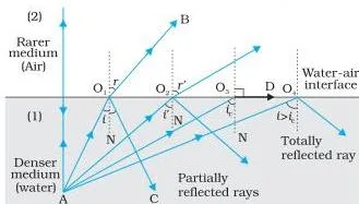
Fig. 9.11 packs three behaviours into one diagram. Ray \( AO_1 \) refracts away from the normal; ray \( AO_3 \) refracts at \( 90^\circ \), grazing the surface at the critical angle; ray \( AO_4 \) cannot refract at all and reflects entirely back into the water.
Reading tip: the direction of bending tells you which medium is denser — bending away from the normal means the second medium is rarer.
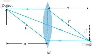
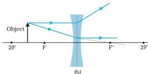
For a convex lens, a ray parallel to the axis bends and passes through the second focus \( F’ \). For a concave lens, the same parallel ray bends away, and its backward extension appears to come from the first focus \( F \). Reading tip: the ray through the optical centre passes straight — draw it first, because it anchors the whole diagram.
Reading the prism plot
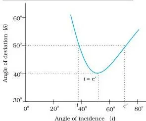
The deviation curve is U-shaped. For almost every value of \( \delta \) there are two angles of incidence — one being \( i \) and the other the corresponding \( e \), because \( i \) and \( e \) are symmetric in \( \delta = i + e – A \). Only at the lowest point, the minimum deviation \( D_m \), is the value unique.
Reading tip: the minimum is where the refracted ray inside the prism runs parallel to the base — that condition gives \( r = A/2 \) and the refractive index formula.
Reading the instrument diagrams
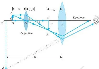
The objective forms a real, inverted, magnified intermediate image of the tiny object; that image sits at or inside the focal plane of the eyepiece, which then acts as a magnifier and forms the enlarged virtual image the eye sees.
Reading tip: split the diagram in two at the intermediate image — the objective side first, the eyepiece side second — and each half is just a diagram you already know.
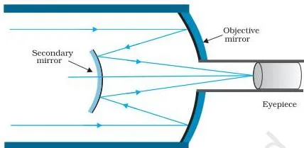
Parallel rays enter and strike the large concave primary mirror, which reflects them toward a small convex secondary; the secondary sends them back through a central hole in the primary to the eyepiece. Reading tip: trace the beam in three straight stretches — in, to the secondary, out through the hole — and you have the whole layout.
Key definitions from this chapter
A quick glossary so you can check a term without hunting through the chapter. Page numbers point to where the book defines it.
| Term | Plain definition | NCERT page |
|---|---|---|
| Ray and beam | A ray is the straight-line path light takes; a bundle of rays is a beam. | p. 220–221 |
| Principal axis | The line joining the pole to the centre of curvature of a spherical mirror (for a lens, the line through the optical centre and principal focus). | p. 222 |
| Pole and optical centre | The geometric centre of a spherical mirror (pole) and of a spherical lens (optical centre). | p. 222 |
| Principal focus and focal length | The point where a parallel paraxial beam converges (concave mirror, convex lens) or appears to diverge from (convex mirror, concave lens); focal length \( f \) is its distance from the pole or optical centre, and \( f = R/2 \) for a mirror. | p. 223 |
| Real and virtual image | Real: rays actually converge at the point. Virtual: rays appear to diverge from the point when produced backwards. | p. 224 |
| Linear magnification | The ratio of image height to object height, \( m = h’/h \); equals \( -v/u \) for a mirror and \( v/u \) for a lens. | p. 225, 235 |
| Refractive index | The constant \( n_{21} \) in Snell’s law, a characteristic of a pair of media and of wavelength, independent of the angle of incidence. | p. 228 |
| Critical angle and total internal reflection | The critical angle \( i_c \) is the angle of incidence for which the angle of refraction is \( 90^\circ \); for larger angles the ray is totally reflected back into the denser medium. | p. 230 |
| Power of a lens | \( P = 1/f \), measured in dioptres (\( 1\ \text{D} = 1\ \text{m}^{-1} \)); positive for a converging lens, negative for a diverging lens. | p. 236 |
| Angle of deviation | The angle between the emergent ray and the direction of the incident ray through a prism; \( \delta = i + e – A \). | p. 239 |
| Magnifying power | The ratio of the angle subtended at the eye by the image to the angle the object subtends at the near point (microscope), or the ratio \( \beta/\alpha = f_o/f_e \) (telescope). | p. 242, 244 |
Common mistakes students make in this chapter
These are the errors the chapter itself flags in its note boxes and Points to Ponder — the places where readers of this chapter routinely go wrong. Each row gives the mistake, the correct rule, and a way to check yourself.
| Mistake | Correct rule | How to check your answer |
|---|---|---|
| Putting \( u \) or \( f \) in as positive for an object in front of a mirror or lens. | Measure from the pole or optical centre. The object is on the incoming-light side, so \( u \lt 0 \); a concave mirror’s focus is also on that side, so \( f \lt 0 \). | For a concave mirror with the object in front, both \( u \) and \( f \) must come out negative — if \( f \) came out positive, you have the wrong mirror. |
| Treating “optically denser” as “heavier”. | Optical density is the ratio of the speed of light in two media, not mass per unit volume. Turpentine has lower mass density than water yet higher optical density. | Ask which medium has the lower speed of light — that one is optically denser, regardless of weight. |
| Thinking the image disappears when the screen is removed. | The rays are still converging at the image point; the screen only diffuses them into your eye. A laser-show image in air needs no screen. | If the image was real, the rays meet at the image point in free space — screen or no screen. |
| Expecting any surface to form an image. | Imaging needs regular reflection or refraction, where all rays from a point reach the same image point. A rough page scatters rays, so you see no image. | Compare a mirror with a page of a book: only the mirror reflects regularly. |
| Confusing linear magnification with angular magnification. | \( m = h’/h \) compares sizes; magnifying power compares angles subtended at the eye. For a simple microscope they differ: \( 1 + D/f \) versus \( D/f \). | If the question says “magnifying power,” it wants the angle ratio, not \( h’/h \). |
| Applying the critical-angle rule in the wrong direction. | Total internal reflection needs light going from optically denser to rarer medium with \( i \gt i_c \). Going rarer to denser, refraction is always possible — no critical angle arises. | \( \sin i_c = n_{21} \) requires \( n_{21} \lt 1 \), which only holds when the second medium is rarer — check the travel direction first. |
How the end of chapter exercises test these ideas
Each exercise belongs to one section. Work through them in this order and you test every topic once, in the same sequence the chapter teaches it.
- Mirror equation — Exercises 9.1 and 9.2 (position, nature and size; what happens as the object moves), 9.15 (deduce image properties algebraically from the mirror equation), 9.30 (deflection of a light spot by a plane mirror).
- Refraction and apparent depth — Exercise 9.3 (refractive index of water from real and apparent depth), 9.4 (Snell’s law across two interfaces), 9.16 (apparent raise of a pin through a glass slab).
- Total internal reflection — Exercise 9.5 (area of the water surface through which light from a bulb emerges), 9.17 (light pipe with and without cladding), 9.21 (incidence angle for total internal reflection at the second face of a prism).
- Prism — Exercise 9.6 (refractive index from minimum deviation; new minimum deviation when the prism sits in water).
- Lens formula and lens maker’s formula — Exercises 9.7 (designing double-convex lenses), 9.8 (lens placed in a convergent beam), 9.9 (concave lens image), 9.10 (two lenses in contact), 9.18 and 9.19 (lens between an object and a screen), 9.20 (effective focal length with lenses 8.0 cm apart), 9.31 (equiconvex lens on a liquid layer over a mirror — the matching-medium idea of Example 9.6).
- Microscope and telescope magnifying power — Exercises 9.11, 9.12 and 9.26 (compound microscope), 9.13, 9.14, 9.27 and 9.28 (telescopes), 9.29 (Cassegrain mirror arrangement).
- Linear versus angular magnification — Exercises 9.22, 9.23 and 9.24 (magnifying glass) and 9.25 (angle subtended by object and image).
What a full answer needs: the book’s own worked solutions state three things separately — position, nature and size. For any numerical, write the sign decision first (“concave mirror, object in front, so \( u = -\ldots \), \( f = -\ldots \)”), substitute into the correct equation, then close with real or virtual, erect or inverted, magnified or diminished, and the actual distance.
One caution: textbook contents and the examinable syllabus are not always identical — check the current official CBSE syllabus for what is examinable this session.
Quick revision summary of the chapter
The chapter’s own Summary condensed into two tables: one comparing mirror and lens behaviour, one listing every key formula in the order the book derives it. Each page number points to where the formula appears.
First, compare the sign of focal length and the image nature across the four components:
| Component | Sign of focal length | Image nature to remember |
|---|---|---|
| Concave mirror | Negative (focus on the object side) | Object beyond the focus: real, inverted. Object between pole and focus: virtual, erect, magnified. |
| Convex mirror | Positive | Always virtual, erect, diminished. |
| Convex lens | Positive | Object beyond the focus: real, inverted. Object within the focus: virtual, erect. |
| Concave lens | Negative | Always virtual, erect, diminished. |
Now the formula map — this is the fastest last-minute revision list:
| Formula | What it gives | NCERT page |
|---|---|---|
| \( \frac{1}{v} + \frac{1}{u} = \frac{1}{f} \) | Mirror equation: object distance \( u \), image distance \( v \), focal length \( f \), all signed. | p. 225 |
| \( m = \frac{h’}{h} = -\frac{v}{u} \) | Linear magnification by a spherical mirror. | p. 226 |
| \( \frac{n_2}{v} – \frac{n_1}{u} = \frac{n_2 – n_1}{R} \) | Refraction at a single spherical surface. | p. 233 |
| \( \frac{1}{f} = (n_{21} – 1)\left(\frac{1}{R_1} – \frac{1}{R_2}\right) \) | Lens maker’s formula: focal length from radii and refractive index. | p. 234 |
| \( \frac{1}{v} – \frac{1}{u} = \frac{1}{f} \) | Thin lens formula: object and image distances. | p. 235 |
| \( m = \frac{h’}{h} = \frac{v}{u} \) | Linear magnification by a lens (note: no minus sign, unlike the mirror). | p. 235 |
| \( P = \frac{1}{f} \) | Power of a lens in dioptres, \( f \) in metres. | p. 236 |
| \( \frac{1}{f} = \frac{1}{f_1} + \frac{1}{f_2} + \cdots \), \( P = P_1 + P_2 + \cdots \) | Thin lenses in contact; magnifications multiply, \( m = m_1 m_2 \cdots \). | p. 238 |
| \( n_{21} = \frac{\sin\left(\frac{A + D_m}{2}\right)}{\sin\left(\frac{A}{2}\right)} \) | Refractive index of a prism from its angle \( A \) and minimum deviation \( D_m \). | p. 240 |
| \( D_m = (n_{21} – 1)A \) | Minimum deviation of a thin prism. | p. 240 |
| \( m = 1 + \frac{D}{f} \) (near point), \( m = \frac{D}{f} \) (infinity) | Simple microscope magnifying power; \( D \approx 25\ \text{cm} \). | p. 242 |
| \( m = \left(\frac{L}{f_o}\right)\left(\frac{D}{f_e}\right) \) | Compound microscope magnifying power, final image at infinity. | p. 243 |
| \( m = \frac{f_o}{f_e} \) | Telescope magnifying power; tube length \( f_o + f_e \). | p. 244 |
Related chapters and resources
This chapter is the first of Part II: it follows the final chapter of Part I, Electromagnetic Waves, and hands over to Chapter 10, Wave Optics, which replaces the ray model with the wave model — the Introduction of this very chapter points forward to Chapter 10.
For more on this book, use the Class 12 Physics notes hub; to move across subjects, use the Class 12 hub or the CBSE notes home page. Earlier Class 12 topics such as the Electrostatic Potential and Capacitance Class 12 notes stay relevant because the sign-convention reasoning you practise here is the same careful style used across the course.
Reference: NCERT Class 12 Physics textbook, chapter 9, official edition on ncert.nic.in.
Sources and data verification
- This page describes the NCERT Class 12 Physics Part II textbook — the Ray Optics and Optical Instruments chapter, Chapter 9 of the book — in the official edition published on ncert.nic.in. Page numbers are the printed page numbers of that edition.
- It covers this one chapter only, not the other chapters of Class 12 Physics or other Class 12 subjects in the CBSE scheme.
- NCERT settles textbook titles, editions and PDFs; CBSE settles the curriculum, syllabus and examinations.
- Textbook contents and the examinable syllabus are not always identical — check the current official CBSE syllabus for what is examinable this session.
Frequently asked questions about Ray Optics and Optical Instruments
What is ray optics and why does Class 12 Physics start this chapter with the ray model of light?
Ray optics is the study of light using the ray model, in which light travels along straight lines. Class 12 Physics opens this chapter with it because the wavelength of visible light (roughly 400–750 nm) is far smaller than everyday objects, so a straight-line picture describes reflection, refraction, image formation and instruments well.
The wave nature of light is then taken up properly in Chapter 10, Wave Optics (NCERT p. 220–221).
What is the mirror equation and how do I apply the sign convention in ray optics class 12?
The mirror equation is \( \frac{1}{v} + \frac{1}{u} = \frac{1}{f} \), with \( u \) the object distance, \( v \) the image distance and \( f \) the focal length.
Apply the Cartesian sign convention first: measure from the pole, count distances against the incident light as negative, so \( u \) is negative for an object in front of the mirror and \( f \) is negative for a concave mirror. Substitute, solve for \( v \), then take \( m = -v/u \): a negative \( m \) means a real, inverted image (NCERT p. 225–226).
What is the difference between a real image and a virtual image in this chapter?
A real image is the point where the rays actually meet after reflection or refraction — it can be caught on a screen. A virtual image is the point from which the rays only appear to diverge when produced backwards — you see it, but no screen placed there will catch it.
For a mirror, a negative \( v \) means the image is on the object side and real; for a convex mirror, \( v \) always comes out positive and the image is virtual, behind the mirror (NCERT p. 224).
Why does total internal reflection happen only when light goes from a denser to a rarer medium?
Because the critical angle exists only when the refracted ray bends away from the normal, which is what a denser-to-rarer crossing does. Then \( r \gt i \), and at \( i = i_c \) the refracted ray grazes the surface at \( 90^\circ \), so \( \sin i_c = n_{21} \) with \( n_{21} \lt 1 \). Beyond \( i_c \) refraction is impossible.
Going the other way, rarer to denser, the ray always bends toward the normal, \( r \lt i \), and a refracted ray exists at every angle — no critical angle arises (NCERT p. 229–230).
What is the difference between the lens maker’s formula and the thin lens formula?
The lens maker’s formula \( \frac{1}{f} = (n_{21} – 1)\left(\frac{1}{R_1} – \frac{1}{R_2}\right) \) connects the focal length to the two radii of curvature and the refractive index — it is the design formula used to make a lens of a chosen focal length.
The thin lens formula \( \frac{1}{v} – \frac{1}{u} = \frac{1}{f} \) is the use formula: once the lens exists, it connects the object and image distances. The book derives both in one chain, from the single-spherical-surface formula applied twice (NCERT p. 234–235).
How do you find the magnifying power of a compound microscope and a telescope?
For a compound microscope with the final image at infinity, \( m = \left(\frac{L}{f_o}\right)\left(\frac{D}{f_e}\right) \), where \( L \) is the tube length between the focal points of the objective and the eyepiece, \( f_o \) and \( f_e \) are their focal lengths, and \( D \approx 25\ \text{cm} \) is the near point.
For a telescope, \( m = \frac{f_o}{f_e} \), simply the ratio of the objective focal length to the eyepiece focal length, and the tube length in normal adjustment is \( f_o + f_e \).
Both rest on one idea: magnifying power is the ratio of the angle the final image subtends at the eye to the angle the object would subtend without the instrument (NCERT p. 243–244).
Explore Class 12 Physics Books
Class 12 Physics on LearnCBSE:
Related chapters: