
Wave Optics is Chapter 10 of the NCERT Class 12 Physics Part II textbook — 19 printed pages, book pages 255 to 273, in the 2026-27 edition. The official wave optics class 12 chapter PDF is right below.
The rest of this page tells you exactly what is in that file — sections, figures and formulas — with the NCERT page number for every idea, so you can decide what to study before you open it.
The chapter uses one construction — Huygens’ — to explain four wave phenomena: reflection and refraction, interference, diffraction and polarisation.
Download the official Wave Optics Class 12 chapter PDF
The file below is the chapter exactly as NCERT publishes it: full derivations, all diagrams and the complete exercise set, in the original layout.
Open the official Wave Optics Class 12 NCERT chapter PDF to read Huygens principle, Snell’s law from wavefronts, Young’s double-slit experiment, single-slit diffraction and polarisation with the diagrams in place — it is the same file the NCERT textbook page links to, so every page number cited here matches it.
| What the chapter holds | Count | Where it is used |
|---|---|---|
| Printed pages | 19 | |
| Sections in the chapter | 11 | |
| Figures with NCERT captions | 18 | |
| Worked examples | 1 | solved step by step in our NCERT Solutions |
| Exercise questions | 5 | answered in our NCERT Solutions |
| Official NCERT PDF | Download the chapter PDF | the chapter exactly as NCERT publishes it |
Wave Optics chapter at a glance
This table lists what the chapter holds — its sections, figures, worked examples and exercise questions — so you can see the shape of the chapter in one scan.
What is inside the NCERT Wave Optics chapter
This roadmap tells you where each idea lives in the book. Every bullet names the topic and the printed pages it occupies, in the order the chapter presents them.
- The corpuscular-versus-wave debate: Descartes (1637), Newton’s Opticks, Huygens’ wave theory (1678), Young’s 1801 interference experiment and Maxwell’s electromagnetic theory of light — pages 255–256.
- Huygens principle and wavefronts: the wavefront definition, spherical and plane waves, secondary wavelets and the envelope construction — page 257.
- Refraction of a plane wave at a denser and a rarer medium, and reflection of plane waves: Snell’s law from wavefront geometry, critical angle, total internal reflection and the law of reflection — pages 258–261.
- Coherent and incoherent addition of waves: superposition, constructive and destructive conditions, the intensity formula, and what happens when sources are incoherent — pages 262–264.
- Interference of light waves and Young’s experiment: why sodium lamps fail, how a single pinhole locks phases, and the fringe position formulas — pages 265–266.
- Diffraction and the single slit: the intensity pattern, the minima condition, and the Feynman note on interference versus diffraction — pages 266–268.
- Polarisation: the transverse nature of light, polaroids, Malus’ law and practical uses — pages 269–271.
- Summary, Points to Ponder and Exercises: pages 272–273.
Key concepts in Wave Optics, explained
The chapter leans on one construction — Huygens’ — to explain four wave phenomena: reflection and refraction, interference, diffraction and polarisation. Each block below explains one idea in original words, with the NCERT page so you can follow along in your book.
Wavefronts and Huygens principle
A wavefront is the chapter’s basic object: a surface on which every point oscillates in phase. Drop a stone on a calm pool — the rings that spread out are wavefronts, because every point on a given ring is the same distance from the splash and therefore moves together (NCERT, p. 257).
A point source gives spherical wavefronts; far away, a small patch of the sphere looks flat, so it is treated as a plane wave (Fig. 10.1). Huygens principle then answers one question: given the wavefront now, where is it after a time τ?
Every point on the present wavefront acts as a fresh source of spherical secondary wavelets of radius \( v\tau \); the common tangent to all of them is the new wavefront (p. 257).
The construction also produces a backward wave. Huygens assumed the secondary wavelets have zero amplitude in the backward direction, which removes it; the absence of a backwave is justified properly only in fuller wave theory. The lines perpendicular to the wavefronts are the rays, and the wave’s energy travels along them.
How Huygens construction gives Snell’s law and the law of reflection
This is the geometric heart of the chapter. A plane wave AB meets the boundary at angle \( i \); in time \( \tau \) the point B reaches C, so \( BC = v_1\tau \). From A, draw a sphere of radius \( v_2\tau \) in the second medium; the tangent from C touches it at E, and CE is the refracted wavefront (NCERT, p. 258).
\[ \sin i = \frac{BC}{AC} = \frac{v_1\tau}{AC}, \qquad \sin r = \frac{AE}{AC} = \frac{v_2\tau}{AC} \]
The two right triangles ABC and AEC share the hypotenuse AC, which gives \( \sin i / \sin r = v_1/v_2 \). Defining refractive index as \( n = c/v \) turns this into \( n_1 \sin i = n_2 \sin r \) — Snell’s law (p. 259).
Notice what the wave model predicts: if light bends toward the normal \( (r \lt i) \), it must be slower in the second medium. The corpuscular model predicted the opposite — faster in the denser medium. Foucault’s 1850 experiment settled it: light in water is slower than in air, so the wave model wins (p. 256).
Two consequences follow. First, the crests must match across the boundary, so \( v_1/\lambda_1 = v_2/\lambda_2 \): when light enters a denser medium its speed and wavelength both fall, but its frequency does not change (p. 259).
Second, at a rarer medium \( (v_2 \gt v_1) \) the wavefront bends away from the normal; when the angle of incidence reaches the critical angle \( \sin i_c = n_2/n_1 \), the refracted ray runs along the boundary, and beyond it you get total internal reflection (p. 260).
For reflection, the same construction gives \( AE = BC = v\tau \), making triangles EAC and BAC congruent, so the angle of incidence equals the angle of reflection — the law of reflection (p. 261).
With these two laws in hand, the behaviour of prisms, lenses and mirrors follows; Fig. 10.7 shows how a thin prism tilts a plane wavefront, a convex lens makes it spherical and converging, and a concave mirror does the same on reflection (p. 261).
Coherent sources, superposition and the intensity formula
Interference only makes sense if you can add waves that keep a fixed phase relationship. Two needles bobbing in phase on a water surface produce exactly that: the phase difference between their waves at any point does not change with time, which is the definition of coherent sources (NCERT, p. 262).
The superposition principle says the resultant displacement is the vector sum of the individual displacements. When the path difference is a whole number of wavelengths \( n\lambda \), the waves arrive in phase, amplitudes add to \( 2a \), and the intensity is \( 4I_0 \) — constructive interference.
When the path difference is \( (n + \frac{1}{2})\lambda \), they arrive in anti-phase, cancel, and the intensity is zero — destructive interference (p. 264).
Why \( 4I_0 \) and not \( 2I_0 \)? Intensity is proportional to the square of amplitude, and two equal in-phase amplitudes give \( (2a)^2 = 4a^2 \). For a general phase difference \( \phi \), the resultant amplitude is \( 2a\cos(\phi/2) \), so \[ I = 4I_0 \cos^2(\phi/2) \]
If the sources are incoherent — their phase difference changes rapidly — the cosine term averages to zero and you get a steady \( 2I_0 \) everywhere: the intensities just add, which is why two lamps on a wall never show fringes (p. 264).
Young’s double slit experiment and fringe spacing
Ordinary sources are the problem: a sodium lamp abruptly changes phase every \( 10^{-10} \) seconds or so, so two independent lamps are incoherent.
Young’s trick was to lock the phases — light from one pinhole S falls on two close pinholes \( S_1 \) and \( S_2 \); because both draw from the same source, any abrupt phase change in S appears identically in both, keeping their phase difference constant (NCERT, p. 265).
The screen then shows alternating bright and dark bands called fringes. A bright fringe appears where the path difference is a whole number of wavelengths, at position \[ x = \frac{n\lambda D}{d}, \qquad n = 0, \pm 1, \pm 2, \dots \]
and a dark fringe where it is a half-integer:
\[ x = (n + \tfrac{1}{2})\frac{\lambda D}{d} \]
Here \( d \) is the slit separation and \( D \) the slit-to-screen distance (p. 266). Because both formulas are linear in \( n \), the fringes are equally spaced — the hallmark of Young’s pattern. A fresh numerical example with the same formula is worked out in the revision section below.
Single slit diffraction: central maximum and weaker secondary maxima
When Young’s double slit is replaced by one narrow slit of width \( a \), the pattern changes character: one broad central bright region with much weaker bands on either side. The slit is treated as many in-phase secondary sources, and their contributions are added with the proper phase differences (NCERT, p. 267).
The results to remember: a central maximum at \( \theta = 0 \); zero intensity at \( \theta \approx n\lambda/a \) for \( n = \pm 1, \pm 2, \pm 3, \dots \); and weaker secondary maxima in between. Note the minima start at \( n = \pm 1 \) — the centre is a maximum, never a minimum.
Energy is only redistributed, never lost, so the bright central band carries what the dark bands remove (p. 268).
The chapter also quotes Feynman: no one has been able to define a satisfactory difference between interference and diffraction — it is a question of usage, with few sources called interference and many sources called diffraction. In fact the double-slit pattern on the screen is a superposition of single-slit diffraction from each slit and the double-slit interference itself (p. 268).
Polarisation and Malus’ law
Polarisation is the evidence that light is transverse. A string shaken up and down carries a displacement perpendicular to its direction of travel, and that wave can be polarised; sound, a longitudinal wave, cannot be polarised at all (NCERT, p. 269).
Light behaves like the string: its electric field is always perpendicular to the direction of propagation, so it is a transverse electromagnetic wave.
A polaroid is a sheet of long chain molecules aligned in one direction; it absorbs the electric-field component along those molecules and transmits the component perpendicular to them — that direction is the pass-axis (p. 270). Light emerging from one polaroid therefore has its electric field confined to a single line: it is linearly polarised, or plane polarised.
Natural light, whose electric vector changes direction randomly, is unpolarised.
When polarised light of intensity \( I_0 \) meets a second polaroid whose pass-axis makes angle \( \theta \), only the component \( E\cos\theta \) gets through, so \( I = I_0\cos^2\theta \) — Malus’ law (p. 270). Crossed polaroids \( (\theta = 90^\circ) \) transmit nothing; a single polaroid always transmits half the incident intensity.
The chapter’s Example 10.2 applies Malus’ law twice: a polaroid rotated between two crossed polaroids transmits \( (I_0/4)\sin^2 2\theta \), which is maximum when \( \theta = 45^\circ \) (p. 271). That is why polaroids control glare in sunglasses, windowpanes, camera filters and 3D movie glasses.
Wave Optics figures: reading the NCERT diagrams
The derivations in this chapter live in its diagrams. Each figure below is reproduced with its NCERT caption, followed by what to look for. Read them in this order and every formula will have a picture attached to it.
Wavefronts and the Huygens construction
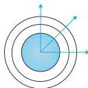
In Fig. 10.1(a), the rings around the point source are spherical wavefronts: every point on one ring is at the same distance from the source, so all points on it oscillate in phase.
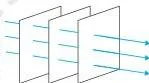
Fig. 10.1(b) shows the key approximation: far from the source, a small patch of a sphere is almost flat, which is why light from a distant star arrives as plane wavefronts.
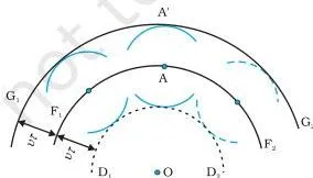
In Fig. 10.2, the middle arc \( F_1F_2 \) is the wavefront at \( t = 0 \); the small circles are secondary wavelets drawn from points on it; the outer arc \( G_1G_2 \), their common tangent, is the wavefront at time \( \tau \). The dashed backwave \( D_1D_2 \) is the part Huygens assumed away.
Refraction and reflection from wavefronts
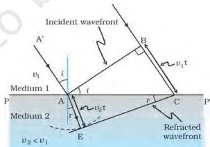
Fig. 10.4 is the whole of Snell’s law. AB reaches the surface at angle \( i \); by the time B has moved the distance \( BC = v_1\tau \), the wavelet from A has grown to radius \( v_2\tau \). The tangent CE is the refracted wavefront, and the two right triangles share AC.
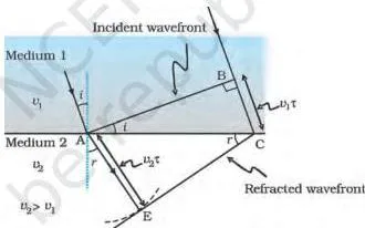
Fig. 10.5 is the rarer-medium case: the second medium has the higher speed, so the refracted wavefront bends away from the normal and \( r \gt i \). Push \( i \) up to the critical angle and beyond, and the wavefront cannot escape — total internal reflection.
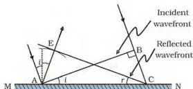
For reflection, Fig. 10.6 draws a wavelet of radius \( v\tau \) from A, equal to BC. Triangles EAC and BAC are congruent, which forces the angle of incidence to equal the angle of reflection.
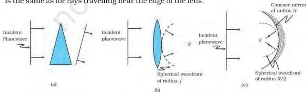
Fig. 10.7 shows what the same geometry means for optical components: a prism delays the lower part of the wavefront and tilts it; a convex lens delays the centre most, turning a plane wave into a spherical one converging at the focus F; a concave mirror does the same by reflection.
Coherent sources and Young’s experiment
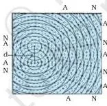
Fig. 10.8(a) is the water-wave model of coherence: two needles bobbing in phase. In Fig. 10.8(b), the solid circles are crests and the dashed circles are troughs; lines of maximum displacement (antinodal) and zero displacement (nodal) are already visible on the water.
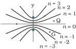
Fig. 10.10 marks the loci where the path difference \( S_1P – S_2P \) equals \( 0, \pm\lambda, \pm2\lambda, \pm3\lambda \). Every point on one curve gives the same path difference, which is why entire curves of constructive interference form.
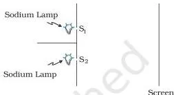
Fig. 10.11 is the negative result that motivates Young’s experiment: two sodium lamps lighting two pinholes give no fringes, because the lamps are incoherent — their phase relation changes every \( 10^{-10} \) second.
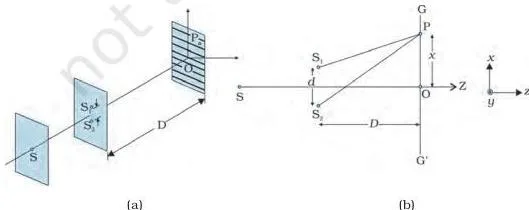
Fig. 10.12 shows Young’s phase-locking arrangement: a single pinhole S illuminates two close pinholes \( S_1 \) and \( S_2 \), and fringes appear on the screen \( GG’ \). Because \( S_1 \) and \( S_2 \) draw from the same source, they stay coherent.
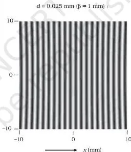
Fig. 10.13 is the computed fringe pattern: straight, equally spaced bands. The caption’s parameters \( d = 0.025\ \text{mm} \), \( D = 5\ \text{cm} \), \( \lambda = 5 \times 10^{-5}\ \text{cm} \) fit the fringe formula for the first few orders.
Single slit diffraction
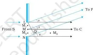
Fig. 10.14 sets up the single slit: the slit LN of width \( a \) is divided into many small parts, all in phase because the incoming wavefront is parallel to the slit plane. Rays to point P make angle \( \theta \) with the normal; adding these contributions with their phase differences gives the minima.
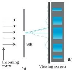
Fig. 10.15 is the pattern you must be able to sketch: a tall central maximum at \( \theta = 0 \), intensity falling to zero at \( \pm\lambda/a, \pm2\lambda/a \), then weaker secondary maxima. The photograph beside the curve shows the same bands.
Polarisation
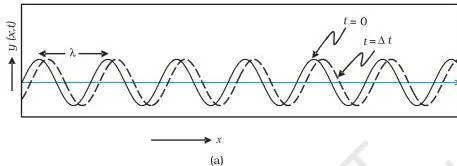
Fig. 10.17 shows a string wave at two instants. The displacement is along \( y \) while the wave travels along \( x \) — perpendicular to the travel, hence transverse. Because the motion stays in one plane, the wave is plane polarised.

Fig. 10.18(a) shows the crossed-polaroid result: through one polaroid the light is steady at half intensity, but with a second polaroid the transmitted fraction falls from full to zero as the angle between the axes goes from \( 0^\circ \) to \( 90^\circ \).
In Fig. 10.18(b), the transmitted electric vector is the component \( E\cos\theta \) along the second pass-axis — the picture behind Malus’ law.
Wave Optics definitions: terms to know before the exam
These are the chapter’s essential terms with the page each is defined on. Learn them in the chapter’s own order — from wavefronts to polarisation.
| Term | Meaning | NCERT page |
|---|---|---|
| Wavefront | A surface of constant phase; every point on it oscillates in phase | p. 257 |
| Secondary wavelets | Spherical waves emitted by each point of a wavefront, of radius \(v\tau\) | p. 257 |
| Spherical / plane wave | Wavefronts from a point source; a small distant patch of them treated as flat | p. 257 |
| Coherent sources | Sources whose phase difference does not change with time | p. 262 |
| Constructive interference | Path difference \(n\lambda\); waves arrive in phase; intensity \(4I_0\) | p. 263 |
| Destructive interference | Path difference \((n + 1/2)\lambda\); waves arrive in anti-phase; zero intensity | p. 264 |
| Fringe | A bright or dark band in an interference pattern; equally spaced in Young’s experiment | p. 266 |
| Diffraction | Spreading of waves around corners, seen in shadows and single-slit patterns | p. 266 |
| Polarisation | Confining the electric-field oscillation to one direction; possible only for transverse waves | p. 269 |
| Linearly / plane polarised wave | A transverse wave whose displacement stays in one plane | p. 269 |
| Pass-axis | The direction of the transmitted electric vector in a polaroid | p. 270 |
| Critical angle | The incidence angle at which the refracted ray grazes the boundary; beyond it, total internal reflection | p. 260 |
Wave Optics formulas: what every symbol means
All of the chapter’s working formulas in one table, with the page where each appears. The middle column tells you what the formula lets you calculate.
| Formula | What it tells you | NCERT page |
|---|---|---|
| \(\frac{\sin i}{\sin r} = \frac{v_1}{v_2}\) | The ratio of the sines of incidence and refraction equals the ratio of wave speeds | p. 259 |
| \(n_1 \sin i = n_2 \sin r\) | Snell’s law in refractive-index form, with \(n = c/v\) | p. 259 |
| \(\sin i_c = \frac{n_2}{n_1}\) | Critical angle for a rarer medium; incidence beyond it gives total internal reflection | p. 260 |
| Path diff \(= n\lambda\) or \((n + \tfrac{1}{2})\lambda\) | Path difference for constructive or destructive interference | p. 264 |
| \(I = 4I_0 \cos^2(\phi/2)\) | Intensity from two equal coherent sources with phase difference \(\phi\) | p. 264 |
| \(x = \frac{n\lambda D}{d}\), \((n + \tfrac{1}{2})\frac{\lambda D}{d}\) | Bright and dark fringe positions in Young’s experiment | p. 266 |
| \(\sin\theta \approx \frac{n\lambda}{a}\) | Single-slit diffraction minima; the central maximum sits at \(\theta = 0\) | p. 267 |
| \(I = I_0 \cos^2\theta\) | Malus’ law: intensity through a polaroid whose axis makes angle \(\theta\) | p. 270 |
Symbol meanings: \( i \) and \( r \) are the angles of incidence and refraction; \( n_1, n_2 \) are refractive indices; \( D \) is the slit-to-screen distance; \( d \) is the slit separation; \( a \) is the slit width; \( \lambda \) is the wavelength; \( \phi \) is the phase difference; \( I_0 \) is the intensity from one source (or the incident polarised intensity in Malus’ law); \( \theta \) is the angle between polaroid pass-axes.
Common mistakes in Wave Optics and how to avoid them
The chapter’s Points to Ponder and worked examples flag the ideas students get wrong. Each row names the mistake, the correct rule, and a quick check.
| Mistake | Correct rule | How to check your answer |
|---|---|---|
| Two sodium lamps will give interference fringes | Ordinary sources change phase abruptly every \(10^{-10}\) s, so they are incoherent and intensities add (\(2I_0\) average) | Ask: could the phase difference between the two lamps stay fixed? If not, no stable fringes (Fig. 10.11) |
| Light slows in water, so it carries less energy | Energy depends on amplitude, not speed; frequency is unchanged | Example 10.1: a slower wave can keep the same amplitude and the same energy (p. 262) |
| The first single-slit minimum is at \(n = 0\) | Minima start at \(n = \pm 1\); \(\theta = 0\) is the central maximum | Put \(n = 0\) into \(\sin\theta \approx n\lambda/a\): it gives \(\theta = 0\), a bright centre — contradiction |
| Interference and diffraction are physically different | Feynman: only a question of usage; the double-slit pattern contains single-slit diffraction | Count the sources: two → interference, many → diffraction (p. 268) |
| Sound can be polarised | Polarisation requires transverse waves; sound is longitudinal | A polaroid has no effect on sound travelling through it |
| Two equal coherent sources give \(2I_0\) | In-phase equal sources give \(4I_0\), because intensity is proportional to amplitude squared | Amplitude \(2a\) squared is \(4a^2\); \(2I_0\) is only the incoherent average (p. 264) |
How to revise Wave Optics for the Class 12 exam
The exercises at the end of the chapter (page 273) map neatly onto the ideas above. Revise the idea first, then attempt the corresponding exercise in chapter order; each row states what a full answer must include.
| Exercise | What it tests | What a full answer includes |
|---|---|---|
| 10.1 | Wavelength, frequency and speed on reflection and refraction | Reflected light keeps all three; refracted light keeps frequency, with speed \(c/n\) and wavelength \(\lambda/n\); state units |
| 10.2 | Wavefront shapes | Spherical from a point source; plane after a convex lens when the source is at its focus; plane (a tiny portion of a sphere) for light from a distant star |
| 10.3 | Speed of light in glass and colour dependence | \(v = c/n = 2 \times 10^8\ \text{m/s}\); speed depends on colour; violet travels slower in a glass prism |
| 10.4 | The Young fringe position formula | Use \(x = n\lambda D/d\) with \(n = 4\); rearrange for \(\lambda\); convert mm and cm to m |
| 10.5 | The intensity formula with path difference | Convert path difference to phase \(\phi = 2\pi \times \text{path}/\lambda\); then \(I = 4I_0\cos^2(\phi/2)\); path \(\lambda\) gives \(K\), so path \(\lambda/3\) gives \(K/4\) |
| 10.6 | Two wavelengths coinciding | Bright fringes from the two wavelengths coincide when \(n_1\lambda_1 = n_2\lambda_2\); find the least common condition |
Worked example: fringe spacing with fresh numbers
Two slits are separated by \(d = 0.40\ \text{mm}\), the screen is \(D = 1.5\ \text{m}\) away, and monochromatic light of wavelength \( \lambda = 600\ \text{nm} \) is used. Find (a) the fringe spacing and (b) the position of the third bright fringe.
Step 1: Convert everything to metres first — a unit error is the most common way to lose this question: \(d = 0.40 \times 10^{-3}\ \text{m}\), \(\lambda = 600 \times 10^{-9}\ \text{m}\), \(D = 1.5\ \text{m}\).
Step 2: Fringe spacing is the distance between successive bright fringes, \(\beta = \lambda D/d\).
Substituting, \[ \beta = \frac{600 \times 10^{-9} \times 1.5}{0.40 \times 10^{-3}} = \frac{9.0 \times 10^{-7}}{4.0 \times 10^{-4}} = 2.25 \times 10^{-3}\ \text{m} = 2.25\ \text{mm} \]
Step 3: The \(n\)-th bright fringe sits at \(x_n = n\lambda D/d = n\beta\).
For the third bright fringe, \(x_3 = 3 \times 2.25\ \text{mm} = 6.75\ \text{mm}\).
Final answer: fringe spacing = 2.25 mm; third bright fringe = 6.75 mm from the central maximum.
Revise in the chapter’s own order: wavefronts and Huygens construction first, then coherent sources and Young’s experiment, then single-slit diffraction, then polarisation — the last two build directly on the first two. Textbook contents and the examinable syllabus are not always identical, so check the current official CBSE syllabus for what is examinable this year.
Try the single slit diffraction experiment at home
The textbook gives an easy way to see diffraction with household items — two razor blades and one clear glass bulb with a straight filament. The filament plays the role of the first slit S, and the lens of your eye focuses the pattern on your retina (NCERT, p. 268).
- Hold two razor blades so their edges are parallel, with a narrow slit between them.
- Keep the slit parallel to the straight filament of a clear glass bulb, right in front of the eye.
- Adjust the slit width and the parallelism of the edges until bright and dark bands appear.
- Use a red or blue filter to make the fringes clearer; with both filters, red fringes appear wider than blue.
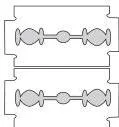
Fig. 10.16 shows the hold; the bands you see this way are the same single-slit pattern the chapter derives. Warning: do not try this with direct sunlight — it can damage the eye, and the Sun subtends too large an angle to give fringes anyway.
What the Wave Optics chapter concludes: key results to remember
These are the chapter’s own conclusions, restated in plain words. If you remember only one list before the exam, make it this one.
- Huygens principle: every point on a wavefront is a source of secondary waves; the new wavefront is their forward envelope, and the construction yields the laws of reflection and refraction.
- Superposition: the interference term matters only when sources share the same frequency and a stable phase difference; otherwise intensities just add.
- Young’s double slit: equally spaced fringes at \(x = n\lambda D/d\) and \((n + \tfrac{1}{2})\lambda D/d\).
- Single slit: a central maximum with intensity zero at \(\pm\lambda/a, \pm2\lambda/a, \dots\) and weaker secondary maxima between; energy is redistributed, never lost.
- Polarisation: natural light is unpolarised; a polaroid transmits only the component along its pass-axis, giving linearly (plane) polarised light; a second polaroid turned through a full rotation shows two maxima and two minima.
- Transverse waves only: polarisation is special to transverse waves like light; sound and other longitudinal waves show no polarisation effects.
- The limit of ray optics: diffraction sets the resolution limit of microscopes and telescopes — the smallest separation they can distinguish is set by the wavelength of light.
Related NCERT Class 12 Physics chapters
Wave Optics sits between two optics chapters in the same book. The previous chapter, Ray Optics and Optical Instruments, builds the ray picture that this chapter refines with wavefronts; the next chapter, Dual Nature of Radiation and Matter, moves to the photon picture where light behaves as particles — the other half of the wave–particle story.
For revision help, start with the Ray Optics and Optical Instruments Class 12 notes, then work through the Class 12 Physics notes page for every chapter, including Current Electricity from Part I. The Class 12 hub and the main CBSE notes page list the other subjects. The official NCERT Class 12 Physics Part II textbook page hosts every chapter of this book.
Sources and data verification
The page references and figure captions on this page describe the NCERT Class 12 Physics Part II textbook, Chapter 10 (Wave Optics) — the same edition identified at the top of this page. This page covers Chapter 10 only; it does not describe the full CBSE syllabus, and textbook contents and the examinable syllabus are not always identical.
- NCERT settles the textbook editions, chapter text and official PDFs; CBSE settles the curriculum, syllabus and examinations.
- This page is maintained for the current academic session using the NCERT information available to us.
- For the authoritative chapter text, open the official PDF from ncert.nic.in linked at the top of this page.
Wave Optics Class 12: frequently asked questions
Why do two sodium lamps not produce interference fringes while two pinholes from one source do?
Two sodium lamps are incoherent. An ordinary source such as a sodium lamp undergoes abrupt phase changes in about \(10^{-10}\) seconds, so two independent lamps never keep a fixed phase relationship; the interference term averages to zero and the intensities simply add.
In Young’s arrangement both pinholes draw light from one source, so any phase change appears identically in both — their phase difference stays constant and stable fringes form (NCERT, p. 265).
Does the wavelength of light change when it enters water, and does the frequency change?
The frequency does not change; the wavelength does. Atoms in the medium oscillate at the frequency of the incident light and re-emit at that same frequency, so \(\nu\) stays the same. Because the speed falls to \(v = c/n\), the wavelength must fall to \(\lambda/n\) to keep \(v = \nu\lambda\) constant (p. 259).
What is the difference between interference and diffraction in the wave optics chapter?
It is a question of usage, not physics — Feynman’s point in the chapter (p. 268). With a few sources, say two, the result is usually called interference; with many sources, diffraction. The double-slit pattern on the screen is actually a superposition of single-slit diffraction from each slit and the double-slit interference pattern.
When the pass axes of two polaroids are crossed, what happens to the transmitted intensity and why?
It becomes zero. Malus’ law, \(I = I_0\cos^2\theta\), gives the transmitted intensity, and for crossed polaroids \(\theta = 90^\circ\), so \(\cos^2\theta = 0\) (p. 270). A polaroid transmits only the electric-field component parallel to its pass-axis; when the axes are crossed, the component along the second axis is zero, so nothing passes.
What is the shape of the wavefront after light passes through a convex lens?
It becomes spherical and converges to the focus. In a convex lens the central part of the incident plane wave traverses the thickest glass and is delayed the most, so the emerging wavefront has a depression at its centre — a spherical wavefront converging at the focus F (p. 261, Fig. 10.7).
The reverse case is Exercise 10.2(b): if a point source sits at the focus, the emerging wavefront is plane.
How can I check the single slit diffraction pattern at home?
Take two razor blades and hold their edges parallel to make a narrow slit; keep it parallel to the straight filament of a clear glass bulb and view the filament through it. Adjust the slit width until bright and dark bands appear; a red or blue filter makes them clearer, and red fringes are wider than blue.
Never use direct sunlight — it can damage the eye (p. 268).
Reference: NCERT Class 12 Physics textbook, chapter 10, official edition on ncert.nic.in.
Explore Class 12 Physics Books
- Previous: Ray Optics and Optical Instruments
- Next: Dual Nature of Radiation and Matter
Class 12 Physics on LearnCBSE:
Related chapters: