
These ray optics and optical instruments class 12 notes compress Chapter 9 of the NCERT Physics Part II textbook onto one revision page: Cartesian sign conventions, spherical mirror and lens formulas, refraction, total internal reflection, prisms, and the microscope and telescope — each with the formula, symbols and units you need.
Revise in three passes. First, read every concept section in order and check each formula against the formula sheet. Second, rework the three worked examples with your own numbers, naming the method before the working. Third, run through the common-mistakes table and the one-page recap the night before the exam.
Every definition, formula and value below is grounded in the NCERT Class 12 Physics Part II textbook, Chapter 9, with page references so you can verify any point against the official NCERT PDF of Chapter 9 (leph201.pdf).
Chapter Map: What These Ray Optics and Optical Instruments Class 12 Notes Cover
The table below lists the chapter in teaching order, so you know what to revise and in what sequence. The sign convention comes first because every formula in the chapter depends on it.
| Concept | The question it answers | NCERT page |
|---|---|---|
| Ray model of light | When does light behave as a straight line instead of a wave? | p. 1 |
| Spherical mirrors: sign convention, \( f = R/2 \), mirror equation | How does a mirror locate an image? | p. 2–6 |
| Refraction, Snell’s law, apparent depth, lateral shift | Why does a pool look shallower than it is? | p. 8–9 |
| Total internal reflection and its applications | When does light refuse to leave a medium? | p. 9–12 |
| Spherical surfaces and lenses: lens maker’s, thin lens, power | How do lenses bend and combine light? | p. 12–18 |
| Prism and minimum deviation | How can a prism measure refractive index? | p. 19–20 |
| Optical instruments: microscope and telescope | How does an instrument magnify an angle? | p. 20–26 |
The Ray Model: When Light Behaves Like a Straight Line
Visible light is an electromagnetic wave of wavelength between about 400 nm and 750 nm (NCERT, p. 1). Chapter 8 shows that light is a wave, yet this chapter treats it as a straight line. The reason: the wavelength is tiny compared with ordinary objects (a few cm or larger), so wave fronts behave like rays.
A ray is the straight path along which light travels from one point to another. A beam is a bundle of such rays. The working speed of light in vacuum is \( c = 3 \times 10^{8}\ \text{m/s} \); the exact measured value is \( c = 2.99792458 \times 10^{8}\ \text{m/s} \) (NCERT, p. 1).
The model has a boundary: when object sizes approach the wavelength, you must switch to the wave picture. That is the subject of the next chapter — you meet it properly in the wave optics class 12 notes, and the wave origin of light itself in the electromagnetic waves class 12 notes.
Spherical Mirrors: Sign Convention, f = R/2 and the Mirror Equation
The pole is the geometric centre of a spherical mirror; the optical centre is the corresponding point of a lens. The line joining the pole and the centre of curvature is the principal axis (NCERT, p. 2).
Under the Cartesian sign convention (NCERT, p. 2):
- All distances are measured from the pole (mirror) or optical centre (lens).
- Distances in the direction of incident light are positive; opposite to it, negative.
- Heights measured upwards are positive; downwards, negative.
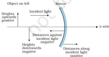
The mirror section studies paraxial rays — rays that strike close to the pole and make small angles with the principal axis. Because of this small-angle assumption, each formula below is exact only for paraxial rays (NCERT, p. 3).
A parallel paraxial beam converges to (or appears to diverge from) the principal focus F; the plane through F normal to the axis is the focal plane.
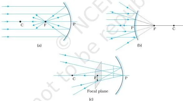
Why f = R/2
A ray parallel to the axis strikes the mirror at M. The radius CM is normal at M, so the angle of incidence is \( \theta \). After reflection the ray passes through F. For paraxial rays \( \tan \theta \approx \theta \) and \( \tan 2\theta \approx 2\theta \), which gives \( FD = CD/2 \).
Since D is very close to P for small \( \theta \), the result is (NCERT, p. 4):
\[ f = \frac{R}{2} \]
The mirror equation and magnification
Using similar triangles in the ray diagram, then applying the sign convention, gives the mirror equation (NCERT, p. 4–5):
\[ \frac{1}{v} + \frac{1}{u} = \frac{1}{f} \]
Here \( u \) is the object distance, \( v \) the image distance, and \( f \) the focal length. Linear magnification is the ratio of image height \( h’ \) to object height \( h \), and for mirrors (NCERT, p. 6):
\[ m = \frac{h’}{h} = -\frac{v}{u} \]
An image is real if reflected (or refracted) rays actually converge to it, and virtual if they only appear to diverge from it when produced backwards (NCERT, p. 4). A negative \( m \) means an inverted, real image; positive \( m \) means an erect, virtual one.
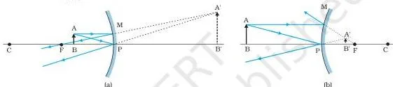
Four convenient rays for mirror ray diagrams
Choose any two of the following to locate an image (NCERT, p. 4):
- Ray parallel to the principal axis — reflected ray passes through F.
- Ray through the centre of curvature C (or appearing to come from it, for a convex mirror) — retraces its path.
- Ray through (or directed towards) F — reflected ray becomes parallel to the principal axis.
- Ray incident at any angle at the pole — follows the laws of reflection.
Sign-convention mnemonic — Mirror brings a Plus and a Minus; the Lens borrows the Minus and leaves the Plus behind. Mirror equation: \( 1/v + 1/u = 1/f \) (plus), magnification \( m = -v/u \) (minus). Lens formula: \( 1/v – 1/u = 1/f \) (minus), magnification \( m = +v/u \) (plain). And for a real object, u is always negative for both mirrors and lenses.
Misconception autopsy: a virtual image can’t be caught on a screen, but you can see and photograph it. For a virtual image, the rays never actually meet — your eye collects them as if they had come from a point behind the mirror or on the object’s side of a lens.
That is exactly how you photograph yourself in a plane or convex mirror. By contrast, a real image exists in space even without a screen; a screen merely diffuses the converging rays, as in a laser show (NCERT, p. 28).
Why rear-view mirrors say “objects are closer than they appear”
A convex mirror always forms an erect, diminished virtual image, giving a wide field of view. Because the image is smaller, the eye judges the object as farther away than it really is. The warning label corrects this misjudgement — the real vehicle is closer than the small image suggests.
Refraction: Snell’s Law, Apparent Depth and Lateral Shift
When a ray crosses into another transparent medium, its direction changes. Refraction is governed by Snell’s law (NCERT, p. 8):
\[ \frac{\sin i}{\sin r} = n_{21} \]
where \( i \) and \( r \) are measured from the normal, and \( n_{21} \) is the refractive index of medium 2 with respect to medium 1. It is a property of the pair of media and depends on wavelength, but not on the angle of incidence.
- If \( n_{21} \gt 1 \), the ray bends towards the normal — medium 2 is optically denser.
- If \( n_{21} \lt 1 \), it bends away from the normal — medium 2 is optically rarer.
Two useful index relations (NCERT, p. 8): \( n_{12} = 1/n_{21} \) and \( n_{32} = n_{31} \times n_{12} \).
Optical density is not mass density. Optical density is the ratio of the speeds of light in the two media. Turpentine has a lower mass density than water but a higher optical density — so mass and optical density can disagree (NCERT, p. 8).
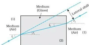
Two slab results follow from Snell’s law (NCERT, p. 9):
- Lateral shift: through a parallel-sided slab, the emergent ray is parallel to the incident ray but displaced sideways.
- Apparent depth: the bottom of a tank appears raised. For viewing near the normal, the apparent depth \( h_1 \) is the real depth \( h_2 \) divided by the refractive index \( n \):
\[ h_1 = \frac{h_2}{n} \]
Total Internal Reflection: The Critical Angle and Its Applications
When light travels from a denser to a rarer medium, part is reflected (internal reflection) and part refracted. As the angle of incidence grows, the refracted ray bends further away from the normal until, at one angle, the ray grazes the interface with \( r = 90^\circ \). That angle is the critical angle \( i_c \).
Beyond it, no refraction is possible and the ray is totally internally reflected — with no transmission at all (NCERT, p. 9–10).
Two conditions must hold for total internal reflection:
- Light travels from a denser to a rarer medium.
- The angle of incidence \( i \) exceeds the critical angle \( i_c \).
From Snell’s law, the critical angle satisfies (NCERT, p. 10):
\[ \sin i_c = n_{21} = \frac{1}{n} \]
where \( n \) is the refractive index of the denser medium with respect to the rarer one. For water against air, \( \sin i_c = 1/1.33 \), so \( i_c = 48.75^\circ \).
D-to-R mnemonic: TIR needs Denser-to-Rarer, and the sine of the critical angle is 1 over n — the rarer-to-denser ratio, never just n.
Critical angles of common transparent media (with respect to air)
| Substance medium | Refractive index | Critical angle |
|---|---|---|
| Water | 1.33 | 48.75° |
| Crown glass | 1.52 | 41.14° |
| Dense flint glass | 1.62 | 37.31° |
| Diamond | 2.42 | 24.41° |
Source: NCERT, Table 9.1, p. 10
Applications of total internal reflection
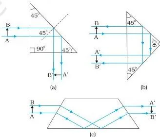
- Prisms that bend light by 90° or 180°, or invert an image without changing its size, use TIR. This works only if \( i_c \lt 45^\circ \), which is true for crown and dense flint glass (NCERT, p. 11).
- Optical fibres have a core of higher refractive index than the cladding. Light undergoes repeated TIR along the fibre, so there is no appreciable intensity loss — even when the fibre is bent, it acts as an optical pipe (NCERT, p. 11).
- Diamond sparkle and mirage are both TIR phenomena: multiple internal reflections in diamond return light to the eye brightly (NCERT, p. 26).

Try it (with care): add a few drops of milk to clear water in a beaker, then shine a laser through it. The beam’s path glows. Aim the beam so it strikes the water surface obliquely and adjust until the refracted spot disappears — that is TIR.
Shine the beam down a long test tube and it bounces internally along the whole tube, exactly as in an optical fibre. Never look into the laser beam or point it at anyone’s face (NCERT, p. 10).
Refraction at Spherical Surfaces: The Road to the Lens Maker’s Formula
A single spherical surface between media of refractive index \( n_1 \) and \( n_2 \), with radius of curvature \( R \), obeys (NCERT, p. 13):
\[ \frac{n_2}{v} – \frac{n_1}{u} = \frac{n_2 – n_1}{R} \]
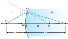
A thin lens is two such surfaces. Applying the surface formula twice and adding gives the lens maker’s formula (NCERT, p. 14):
\[ \frac{1}{f} = (n_{21} – 1)\left( \frac{1}{R_1} – \frac{1}{R_2} \right) \]
For a double convex lens, \( R_1 \) is positive and \( R_2 \) negative; for a concave lens, \( R_1 \) is negative and \( R_2 \) positive, so \( f \) turns out negative. The thin lens formula (NCERT, p. 15) is:
\[ \frac{1}{v} – \frac{1}{u} = \frac{1}{f}, \qquad m = \frac{v}{u} \]
A lens has two foci, F and F’, equidistant from the optical centre. The first focal point is on the side of the original source of light; the second focal point is on the other side (NCERT, p. 14–15).
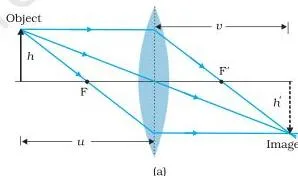
Three convenient rays for lens ray diagrams
- Ray parallel to the principal axis — passes through the second focus F’ (convex) or appears to diverge from the first focus F (concave).
- Ray through the optical centre — emerges undeviated.
- Ray through the first focus (convex) — emerges parallel to the axis; a ray directed at the second focus (concave) also emerges parallel.
Power of a lens
Power measures how strongly a lens converges or diverges light (NCERT, p. 16):
\[ P = \frac{1}{f} \qquad (1\ \text{D} = 1\ \text{m}^{-1}) \]
Power is positive for a converging lens and negative for a diverging lens. A prescription of +2.5 D means a convex lens of focal length +40 cm; −4.0 D means a concave lens of focal length −25 cm. Convert focal length to metres before computing power in dioptres.
Combinations of thin lenses in contact
For lenses of focal lengths \( f_1, f_2, f_3, \dots \) in contact, the effective focal length, power and magnification are (NCERT, p. 17–18):
\[ \frac{1}{f} = \frac{1}{f_1} + \frac{1}{f_2} + \frac{1}{f_3} + \dots, \qquad P = P_1 + P_2 + P_3 + \dots, \qquad m = m_1 m_2 m_3 \dots \]
The power sum is algebraic: convex lenses contribute positive, concave lenses negative. One idea worth knowing: if the lens is immersed in a liquid of the same refractive index (\( n_1 = n_2 \)), then \( 1/f = 0 \), so \( f \to \infty \) and the lens behaves like a plane glass sheet — it disappears (NCERT, Example 9.6, p. 16).
Where the plus and minus signs live: mirror equation vs lens formula vs surface formula
| Equation | Form | Where the minus sits |
|---|---|---|
| Mirror equation | \( \frac{1}{v} + \frac{1}{u} = \frac{1}{f} \) | Plus joins \( u \) and \( v \); magnification carries the minus: \( m = -v/u \) |
| Thin lens formula | \( \frac{1}{v} – \frac{1}{u} = \frac{1}{f} \) | Minus sits before \( u \); magnification is plain: \( m = +v/u \) |
| Spherical surface formula | \( \frac{n_2}{v} – \frac{n_1}{u} = \frac{n_2 – n_1}{R} \) | Minus before the \( n_1/u \) term, with refractive indices attached |
Decision table: the two easiest rays to draw
| Situation | Two easiest rays | Why they are easy |
|---|---|---|
| Mirror, object on axis, real image | Ray parallel to axis + ray through C | Parallel ray reflects through F; the C-ray retraces itself |
| Mirror, object between P and F (virtual image) | Ray parallel to axis + ray appearing to come from C | The C-ray is drawn as if from behind the mirror |
| Convex mirror, any position | Ray parallel to axis + ray toward C | Both reflected rays diverge; extend them backward to meet |
| Any lens | Ray parallel to axis + ray through optical centre | The second ray is a straight undeviated line |
| Lens with awkward F position off-page | Ray through optical centre + ray incident at the pole (mirror) or lens centre | No focus line needed, only the undeviated ray plus one reflection/refraction |
Prism: Deviation, Minimum Deviation and Refractive Index
For a triangular prism of refracting angle \( A \), the geometry of the two faces gives (NCERT, p. 19):
\[ r_1 + r_2 = A, \qquad \delta = i + e – A \]
where \( i \) and \( e \) are the incidence and emergence angles, and \( \delta \) is the total angle of deviation. Because \( \delta = i + e – A \) is symmetric in \( i \) and \( e \), any given deviation (except the minimum) corresponds to two values of \( i \); interchanging \( i \) and \( e \) leaves \( \delta \) unchanged.
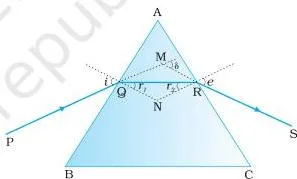
At minimum deviation, the ray inside the prism is parallel to the base, \( i = e \) and \( r_1 = r_2 = A/2 \). The refractive index is then (NCERT, p. 20):
\[ n = \frac{\sin\left( \frac{A + D_m}{2} \right)}{\sin\left( \frac{A}{2} \right)} \]
This is the practical method of measuring refractive index: measure \( A \) and \( D_m \) in the lab and substitute. For a thin prism the angles are small, and the formula collapses to (NCERT, p. 20):
\[ D_m \approx (n_{21} – 1)A \]
Thin prisms deviate light only slightly.
Optical Instruments: Simple Microscope, Compound Microscope and Telescope
The least distance of distinct vision is \( D = 25\ \text{cm} \). Instruments magnify by letting you bring a small object closer than \( D \) and then viewing the enlarged image at a comfortable distance.
The useful quantity is angular magnification (magnifying power) — the ratio of the angle subtended by the image to the angle subtended by the object at the eye — not linear magnification alone.
Simple microscope (magnifying glass)
A converging lens of small focal length held close to the eye gives an erect, virtual image (NCERT, p. 21–22):
- Image at the near point (some eye strain): \( m = 1 + \dfrac{D}{f} \).
- Image at infinity (relaxed eye): \( m = \dfrac{D}{f} \).
With \( D = 25\ \text{cm} \), a lens of \( f = 5\ \text{cm} \) gives about 6× magnification.
Compound microscope
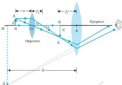
The objective (small \( f_o \)) forms a real, inverted, magnified image; the eyepiece (small \( f_e \)) acts as a magnifier on it. The tube length \( L \) is the distance between the second focal point of the objective and the first focal point of the eyepiece. Total magnifying power (NCERT, p. 24):
\[ m = \frac{L}{f_o} \times \frac{D}{f_e} \]
The final image is inverted. With \( f_o = 1\ \text{cm} \), \( f_e = 2\ \text{cm} \), \( L = 20\ \text{cm} \): \( m = \tfrac{20}{1} \times \tfrac{25}{2} = 250 \).
Refracting telescope
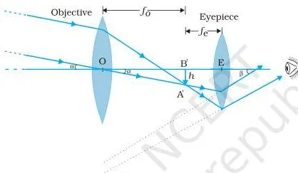
The telescope magnifies distant objects. Its objective has a large focal length and large aperture; the eyepiece has a small focal length. Magnifying power and tube length (NCERT, p. 24–25):
\[ m = \frac{f_o}{f_e}, \qquad \text{tube length} = f_o + f_e \]
If \( f_o = 100\ \text{cm} \) and \( f_e = 1\ \text{cm} \), then \( m = 100 \). A pair of stars \( 1′ \) apart appears separated by \( 100 \times 1′ = 100′ = 1.67^\circ \).
Why large modern telescopes use mirrors
Light-gathering and resolving power both depend on the objective’s diameter, so objectives should be huge. Large lenses sag under their own weight, are expensive, and suffer chromatic aberration. A concave mirror has no chromatic aberration and can be supported over its whole back, not just the rim (NCERT, p. 25–26).
In the Cassegrain arrangement, a convex secondary mirror sends the light through a hole in the primary, giving a long focal length in a short tube. Examples: Yerkes 1.02 m lens; Mt Palomar 5.08 m; Kavalur (India) 2.34 m; Keck pair 10 m each (NCERT, p. 25–26).
Microscope versus telescope at a glance
| Feature | Compound microscope | Telescope |
|---|---|---|
| Purpose | Magnify a small, near object | Magnify a distant object’s angle |
| Objective focal length | Short \( f_o \) | Large \( f_o \) and large aperture |
| Eyepiece focal length | Short \( f_e \) | Short \( f_e \) |
| Final image | Virtual, inverted | Virtual, inverted |
| Magnifying power | \( m = \dfrac{L}{f_o} \times \dfrac{D}{f_e} \) | \( m = \dfrac{f_o}{f_e} \) |
| Tube length | \( L \) (between foci) | \( f_o + f_e \) |
Both microscope focal lengths must be short to make \( m \) large; the telescope objective must be large to gather light and resolve closely spaced objects (NCERT, p. 24–25).
Key Terms and Definitions at a Glance
| Term | Meaning | Example |
|---|---|---|
| Ray | Straight path along which light travels | Laser beam drawn as a single line |
| Beam | Bundle of rays | Torchlight cone |
| Pole | Geometric centre of a spherical mirror | Centre point of a concave shaving mirror |
| Optical centre | Geometric centre of a lens | Centre of a spectacle lens |
| Principal axis | Line joining pole and centre of curvature | The symmetry line of a mirror |
| Focal length | Distance from pole/optical centre to focus | \( f = R/2 \) for a mirror |
| Focal plane | Plane through F, normal to the axis | Where a tilted parallel beam focuses |
| Real image | Rays actually converge to the point | Image on a cinema screen |
| Virtual image | Rays appear to diverge from the point | Image of a car in a convex rear-view mirror |
| Magnification | Ratio of image height to object height | \( m = -v/u \) for mirrors |
| Refractive index | Ratio of speeds of light in two media; \( n_{21} = \sin i / \sin r \) | Water 1.33, crown glass 1.52 |
| Critical angle | Angle of incidence giving \( r = 90^\circ \) | Water 48.75°, diamond 24.41° |
| Total internal reflection | Complete reflection, denser to rarer, \( i \gt i_c \), no transmission | Light pipe in endoscopy |
| Power of a lens | \( P = 1/f \) in dioptres, positive converging, negative diverging | +2.5 D spectacle lens, \( f = +40\ \text{cm} \) |
| Near point | Closest comfortable viewing distance, \( D = 25\ \text{cm} \) | Where a simple microscope places the image |
| Tube length | Distance between the two relevant focal points of a compound microscope | \( L = 20\ \text{cm} \) in the worked example |
| Angular magnification | Ratio of the angle subtended by the image to that by the object | Telescope \( m = f_o/f_e \) |
Formula Sheet with Symbols and Units
| Formula | Meaning of symbols | Units / sign notes | NCERT page |
|---|---|---|---|
| \( f = \dfrac{R}{2} \) | \( R \) = radius of curvature | m or cm; concave mirror \( f \lt 0 \), convex \( f \gt 0 \) | p. 4 |
| \( \dfrac{1}{v} + \dfrac{1}{u} = \dfrac{1}{f} \) | \( u \) object, \( v \) image, \( f \) focal length (mirror) | m; real object \( u \lt 0 \), concave \( f \lt 0 \) | p. 5 |
| \( m = -\dfrac{v}{u} \) | Linear magnification (mirror) | dimensionless; negative = inverted/real | p. 6 |
| \( \dfrac{\sin i}{\sin r} = n_{21} \) | Angles with the normal; \( n_{21} \) index of medium 2 w.r.t. 1 | \( n \) dimensionless | p. 8 |
| \( n_{12} = \dfrac{1}{n_{21}} \) | Reciprocal indices | dimensionless | p. 8 |
| \( h_1 = \dfrac{h_2}{n} \) | \( h_1 \) apparent, \( h_2 \) real depth | m or cm | p. 9 |
| \( \sin i_c = \dfrac{1}{n} \) | Critical angle; \( n \) denser-medium index | degrees; diamond ≈ 24.4° | p. 10 |
| \( \dfrac{n_2}{v} – \dfrac{n_1}{u} = \dfrac{n_2 – n_1}{R} \) | Single spherical surface | m; apply sign convention to \( u, v, R \) | p. 13 |
| \( \dfrac{1}{f} = (n_{21} – 1)\left( \dfrac{1}{R_1} – \dfrac{1}{R_2} \right) \) | Lens maker’s formula | m; \( R_1 \gt 0, R_2 \lt 0 \) for double convex | p. 14 |
| \( \dfrac{1}{v} – \dfrac{1}{u} = \dfrac{1}{f} \) | Thin lens formula | m; convex \( f \gt 0 \), concave \( f \lt 0 \) | p. 15 |
| \( m = \dfrac{v}{u} \) | Magnification (lens) | dimensionless; positive = erect/virtual | p. 16 |
| \( P = \dfrac{1}{f} \) | Power of a lens | dioptre; \( 1\ \text{D} = 1\ \text{m}^{-1} \) | p. 16 |
| \( \dfrac{1}{f} = \dfrac{1}{f_1} + \dfrac{1}{f_2} + \dots \) | Lenses in contact | m; algebraic sum of inverses | p. 17 |
| \( P = P_1 + P_2 + \dots \) | Net power of combination | D; algebraic sum | p. 18 |
| \( m = m_1 m_2 \dots \) | Total magnification | dimensionless | p. 18 |
| \( r_1 + r_2 = A \) | Prism geometry | degrees | p. 19 |
| \( \delta = i + e – A \) | Total deviation | degrees | p. 19 |
| \( n = \dfrac{\sin\left( \frac{A + D_m}{2} \right)}{\sin\left( \frac{A}{2} \right)} \) | Prism refractive index at minimum deviation | dimensionless; \( D_m \) measured in lab | p. 20 |
| \( D_m \approx (n_{21} – 1)A \) | Thin prism | degrees; small \( A \) | p. 20 |
| \( m = 1 + \dfrac{D}{f} \), \( m = \dfrac{D}{f} \) | Simple microscope, near point / infinity | \( D = 25\ \text{cm} \) | p. 22 |
| \( m = \dfrac{L}{f_o} \times \dfrac{D}{f_e} \) | Compound microscope | \( L \) = tube length | p. 24 |
| \( m = \dfrac{f_o}{f_e} \) | Telescope, tube length \( f_o + f_e \) | dimensionless | p. 24–25 |
Worked Examples: Problems With Numbers You Haven’t Seen Before
Example 1: Concave mirror — position, nature and magnification
Method: mirror equation with the Cartesian sign convention.
Equation: \( \frac{1}{v} + \frac{1}{u} = \frac{1}{f} \).
- Step 1: A concave mirror has radius of curvature \( R = 24\ \text{cm} \), so \( f = R/2 = 12\ \text{cm} \), and for a concave mirror \( f = -12\ \text{cm} \).
- Step 2: The object is 18 cm in front, so \( u = -18\ \text{cm} \) (opposite to incident light).
Substitute:
\[ \frac{1}{v} + \frac{1}{-18} = \frac{1}{-12} \]
Step 3: Solve for \( v \):
\[ \frac{1}{v} = -\frac{1}{12} + \frac{1}{18} = \frac{-3 + 2}{36} = -\frac{1}{36} \qquad \Rightarrow \qquad v = -36\ \text{cm} \]
Step 4: Magnification \( m = -v/u = -(-36)/(-18) = -2 \).
Final answer: Image is 36 cm in front of the mirror, real, inverted and magnified 2 times.
Example 2: Lens maker’s formula plus a lens combination with power
Method: lens maker’s formula, then the algebraic power sum for lenses in contact.
Step 1: An equiconvex lens has \( n = 1.5 \), \( R_1 = +20\ \text{cm} \), \( R_2 = -20\ \text{cm} \).
\[ \frac{1}{f} = (1.5 – 1)\left( \frac{1}{20} – \frac{1}{-20} \right) = 0.5 \times \frac{2}{20} = \frac{1}{20} \qquad \Rightarrow \qquad f = +20\ \text{cm} \]
- Step 1: Convert to metres: \( f = 0.20\ \text{m} \), so \( P_1 = 1/0.20 = +5\ \text{D} \).
- Step 2: Add a concave lens \( f_2 = -30\ \text{cm} = -0.30\ \text{m} \), \( P_2 = -1/0.30 \approx -3.33\ \text{D} \).
Net power \( P = 5 – 3.33 \approx +1.67\ \text{D} \).
Step 4: Effective focal length \( 1/f = 1/20 – 1/30 = 1/60 \), so \( f = +60\ \text{cm} \).
Final answer: The combination is converging, with \( f = +60\ \text{cm} \) and \( P \approx +1.67\ \text{D} \).
Example 3: Prism at minimum deviation — refractive index
Method: the minimum-deviation formula \( n = \dfrac{\sin\left( \frac{A + D_m}{2} \right)}{\sin\left( \frac{A}{2} \right)} \).
- Step 1: Prism angle \( A = 60^\circ \), measured minimum deviation \( D_m = 38^\circ \).
- Step 2: Compute \( (A + D_m)/2 = 49^\circ \) and \( A/2 = 30^\circ \).
\[ n = \frac{\sin 49^\circ}{\sin 30^\circ} = \frac{0.7547}{0.5} \approx 1.51 \]
Final answer: The refractive index of the prism material is about 1.51.
All three examples assume paraxial rays and thin lenses in contact, exactly as the formulas require.
Common Mistakes in Ray Optics (and the Corrections)
| Students write… | Correct is… | How to check your answer |
|---|---|---|
| Mirror formula as \( \frac{1}{v} – \frac{1}{u} = \frac{1}{f} \) | Mirror equation uses a plus: \( \frac{1}{v} + \frac{1}{u} = \frac{1}{f} \). The minus belongs to the lens formula. | Substitute a real-image case: with \( u = -20\ \text{cm}, f = -10\ \text{cm} \), plus-sign form gives \( v = -20\ \text{cm} \). |
| Concave mirror \( f \) taken positive | \( f \) is negative for concave, positive for convex (NCERT, p. 26). | Concave focuses in front (object side, negative); convex’s virtual focus is behind (positive). |
| Object distance \( u \) taken positive | For a real object, \( u \) is negative under the Cartesian convention. | Object side is opposite to incident light, so it is always negative. |
| \( m = v/u \) used for mirrors | Mirrors use \( m = -v/u \); lenses use \( m = +v/u \). | A real inverted mirror image must give negative \( m \); the minus delivers it. |
| \( \sin i_c = n \) | \( \sin i_c = 1/n \) — the rarer-to-denser ratio. | For water, \( 1/1.33 = 0.7519 \), which equals \( \sin 48.75^\circ \). |
| Optical density = mass density | Optical density is the speed-of-light ratio; turpentine is lighter than water but optically denser (NCERT, p. 8). | Compare t |
| Half the mirror covered → half the image | The image stays complete; only its intensity drops to half. | Laws of reflection still hold at every remaining point (NCERT, Example 9.1, p. 6). |
| Lens power from focal length in cm | Convert to metres first: \( 1\ \text{D} = 1\ \text{m}^{-1} \). | \( f = 20\ \text{cm} = 0.2\ \text{m} \Rightarrow P = +5\ \text{D} \). |
Why each correction holds: the sign rules come from the direction of incident light, and every formula is just the sign-convention audit of the geometry — so one wrong sign flips the whole answer.
Exam Notes: Answers That Earn the Marks
- Show the sign explicitly. Writing \( u = -18\ \text{cm} \) with the minus shown is the step that earns the first mark in numericals — never write bare magnitudes.
- Know the heavy derivations: the mirror equation from similar triangles (p. 4–5), the lens maker’s formula from the two-surface model (p. 14), the prism minimum-deviation formula (p. 20), and the telescope magnifying power (p. 24).
- Ray diagram conventions: always draw two convenient rays with arrowheads, and label \( F \), \( P \), and the image position — labels earn the diagram mark.
- Conceptual short-answer favourites: why a pool appears shallower (apparent depth), why optical fibres transmit without intensity loss (repeated TIR), why convex mirrors suit rear-view use (wide field, erect diminished virtual image), why a diamond sparkles (small \( i_c \approx 24.4^\circ \)).
- Points to Ponder ideas: a real image exists in space even without a screen — the screen merely diffuses the rays, as in a laser show; and image formation needs regular reflection/refraction, which is why you cannot see your image on a rough page (NCERT, p. 28).
For the full set of chapter exercises, practise against the original NCERT Chapter 9 PDF — and for a wider revision sweep, the Class 12 Physics notes page links every chapter in the syllabus.
One-Page Revision Recap: The Chapter in 60 Seconds
| Topic | Governing formula | Key condition |
|---|---|---|
| Reflection | Mirror equation \( \frac{1}{v} + \frac{1}{u} = \frac{1}{f} \), \( f = R/2 \), \( m = -v/u \) | Concave \( f \lt 0 \), convex \( f \gt 0 \); paraxial rays |
| Refraction | \( \sin i / \sin r = n_{21} \), apparent depth \( h_1 = h_2/n \) | Angles from the normal |
| Total internal reflection | \( \sin i_c = 1/n \) | Denser to rarer and \( i \gt i_c \) |
| Lenses | Lens maker’s \( \frac{1}{f} = (n_{21} – 1)(\frac{1}{R_1} – \frac{1}{R_2}) \), \( \frac{1}{v} – \frac{1}{u} = \frac{1}{f} \), \( P = 1/f \) | \( 1\ \text{D} = 1\ \text{m}^{-1} \); convex \( f \gt 0 \), concave \( f \lt 0 \) |
| Prism | \( r_1 + r_2 = A \), \( \delta = i + e – A \), \( n = \frac{\sin((A + D_m)/2)}{\sin(A/2)} \) | Minimum deviation: \( i = e \), ray parallel to base |
| Instruments | Microscope \( m = \frac{L}{f_o} \times \frac{D}{f_e} \); telescope \( m = \frac{f_o}{f_e} \) | \( D = 25\ \text{cm} \); telescope tube \( f_o + f_e \) |
Five facts to know cold: \( c = 3 \times 10^{8}\ \text{m/s} \); least distance of distinct vision \( D = 25\ \text{cm} \); \( 1\ \text{D} = 1\ \text{m}^{-1} \); diamond critical angle ≈ 24.4°; telescope magnifying power = \( f_o/f_e \).
Related study material: Class 12 notes for all subjects, and the full CBSE notes hub.
Ray Optics Questions Students Ask Before the Exam
Why is the focal length of a concave mirror negative and of a convex mirror positive?
Distances measured opposite to the incident light are negative. A concave mirror’s focus lies in front of the mirror, on the object side — opposite to the direction of incident light — so \( f \) is negative. A convex mirror’s virtual focus lies behind the mirror, in the direction of incident light, so \( f \) is positive.
What is the difference between magnification and magnifying power in a microscope?
Magnification is the ratio of image size to object size, \( m = h’/h \). Magnifying power (angular magnification) is the ratio of the angle subtended by the image to the angle subtended by the object at the eye. A microscope increases the angle a tiny object subtends, which is why angular magnification is the relevant quantity.
Why does a diamond sparkle more than a piece of glass of the same shape?
Diamond has a very high refractive index (2.42) and therefore the smallest critical angle in Table 9.1, about 24.4°. Light entering the diamond is totally internally reflected many times before escaping at specific angles, returning brightly to the eye. Glass with a larger critical angle lets much more light escape, so it sparkles less.
Can total internal reflection take place when light travels from air into glass?
No. TIR requires light to travel from a denser to a rarer medium and the angle of incidence to exceed the critical angle. From air into glass, light bends towards the normal and a refracted ray is always possible — there is no rarer-to-denser total internal reflection.
Why is a convex mirror used as a rear view mirror in vehicles?
A convex mirror forms an erect, diminished virtual image and gives a wide field of view, letting the driver see a large area behind. Because the image is smaller, the objects appear farther away than they are — hence the warning that objects in the mirror are closer than they appear.
How can I tell whether an image is real or virtual from the sign of the image distance?
For a mirror, \( v \) negative means a real image in front (object side) and \( v \) positive means a virtual image behind. For a lens, \( v \) positive means a real image on the other side of the lens and \( v \) negative means a virtual image on the same side as the object.
The sign tells you on which side the rays actually converge.
Reference: NCERT Class 12 Physics textbook, chapter Ray Optics and Optical Instruments.
Explore Class 12 Physics Notes
More for this chapter:
Class 12 Physics on LearnCBSE:
Related chapters: