This page carries the official magnetic effects of electric current class 10 chapter as NCERT prints it: Class 10 Science, Chapter 12, Magnetic Effects of Electric Current, 13 printed pages (pp. 195–207) of the rationalised edition.
The NCERT-published PDF sits directly below, free from ncert.nic.in; under it you will find what the chapter covers, what every figure shows, and how the exercises test it.
Download the official magnetic effects of electric current class 10 PDF
The file below is the chapter exactly as printed — text, activities, figures and exercises — and it is the same magnetic effects of electric current class 10 chapter PDF published free by NCERT for students and teachers. Open it to read Section 12.1 on magnetic fields, the seven activities, both worked examples, and the chapter-end exercises in their original layout.
Chapter 12 at a glance: sections, figures and exercises
The official file holds the complete chapter — numbered sections, activities, diagrams, worked examples and question sets. The at-a-glance table below shows how much of each the chapter contains; everything after it explains what that content teaches.
| What the chapter holds | Count | Where it is used |
|---|---|---|
| Printed pages | 13 | |
| Sections in the chapter | 8 | |
| Figures with NCERT captions | 14 | |
| Worked examples | 2 | solved step by step in our NCERT Solutions |
| Exercise questions | 9 | answered in our NCERT Solutions |
| In-text questions | 12 | |
| Activities | 7 | |
| Official NCERT PDF | Download the chapter PDF | the chapter exactly as NCERT publishes it |
What this chapter covers: one story from compass to house wiring
One idea carries the whole chapter: an electric current produces a magnetic field, and that field can push things — including the wires that carry the current.
The chapter builds the idea in four steps: what a magnetic field is, what shape the field takes around different conductors, how a magnetic field pushes a current-carrying wire, and how the same physics keeps a house’s wiring safe.
The four numbered sections of the chapter, in order, are:
- 12.1 Magnetic field and field lines (pp. 196–197) — what a magnetic field is and how field lines picture it.
- 12.2 Magnetic field due to a current-carrying conductor (pp. 197–201) — the field around a straight wire (right-hand thumb rule), a circular loop and a solenoid.
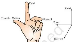
- 12.3 Force on a current-carrying conductor in a magnetic field (pp. 202–203) — how a field pushes a wire, with Fleming’s left-hand rule.
- 12.4 Domestic electric circuits (pp. 204–205) — live, neutral and earth wires, the fuse, and protection against short circuit and overloading.
The chapter’s activities read as one continuous storyline. Activity 12.1 gives the first observation: a compass needle deflects near a current-carrying wire (p. 195). Activities 12.2 and 12.3 draw the bar magnet’s field lines with iron filings and a compass. Activities 12.4 and 12.5 show the straight wire’s concentric field and prove that reversing the current reverses the field (p. 198).
Activity 12.6 maps the field of a circular coil (p. 201), and Activity 12.7 shows a rod being pushed sideways inside a magnetic field (p. 202).
Two extras frame the physics. The chapter opens with Hans Christian Oersted’s 1820 discovery that a current deflects a compass needle — the first proof that electricity and magnetism are linked (p. 195). It closes with a “Magnetism in medicine” box on the body’s own weak magnetic fields and MRI (p. 204).
Worked Example 12.1 applies the right-hand thumb rule to a power line and Example 12.2 applies Fleming’s left-hand rule to an electron entering a magnetic field.
Key concepts: field lines, the hand rules and safe wiring
Five ideas carry the chapter, each explained below in the order the book presents them. Every block opens with what the idea is and why the chapter needs it, then gives the rule and the reasoning behind it.
Magnetic field and field lines: the picture language of magnetism
A compass needle turns near a bar magnet not because anything touches it, but because the magnet fills the space around it with an invisible influence. That region, in which the magnet’s force can be detected, is the magnetic field (NCERT, p. 196).
The compass needle is itself a small bar magnet, and the end that points north is called its north pole (p. 196).
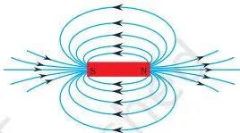
Magnetic field lines are the drawing of that field. By convention, outside the magnet the lines emerge from the north pole and merge at the south pole; inside the magnet they run from south to north. That makes every field line a closed curve (p. 197). Three properties of these lines decide most questions on this section:
- Direction: a field line points the way a north pole would move — outside the magnet, from north to south (p. 197).
- Strength: lines drawn closer together mean a stronger field; the field is strongest near the poles, where the lines crowd (p. 197).
- No crossing: two field lines never intersect, because a compass needle at one point cannot point in two directions at once (p. 197).
The section’s in-text question asks why a compass needle gets deflected when brought near a bar magnet. The answer: the magnet’s field exerts a force on the needle, which is itself a small magnet, so the needle swings to line up with the field where it stands.
The straight wire: concentric field lines and the right-hand thumb rule
Around a straight wire the field already has a shape worth memorising. Activity 12.5’s iron filings line up as concentric circles centred on the wire (p. 198). Two strength facts come from the same activity: the field grows as the current increases, and it weakens as you move away from the wire (p. 198).
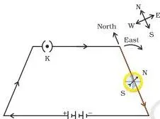
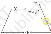
Activity 12.4 adds the direction fact: reversing the current makes the needle deflect the opposite way, so the field reverses with the current (p. 198).
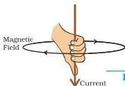
The right-hand thumb rule gives the field’s direction in one step: hold the wire in your right hand with the thumb pointing along the conventional current; your fingers curl in the direction of the magnetic field lines (NCERT, p. 199).
The book notes the same rule is also called Maxwell’s corkscrew rule — if you drive a corkscrew in the current’s direction, it rotates the way the field circles the wire (p. 200). The book’s Example 12.1 applies the rule to an east–west power line; the same reasoning with different directions follows.
Worked example — a north–south power line.
Step 1: Fix the geometry.
The wire lies horizontal, aligned with the north–south line on the ground, and the conventional current flows from north to south.
Step 2: Apply the right-hand thumb rule.
Point the right thumb along the current, so the thumb points south.
Step 3: Read the curl of the fingers.
With the thumb pointing south, the fingers sweep over the top of the wire towards the west, and under the wire towards the east.
Final answer: the magnetic field directly above the wire points west, and directly below the wire it points east.
Circular loop and solenoid: making the field stronger
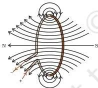
Bend the straight wire into a circle and something useful happens: at the centre of the loop, the circular field lines of each small section of wire straighten out, and every section pushes the field in the same direction inside the loop (p. 200).
The more turns, the more the contributions add — a coil of \(n\) turns produces a field \(n\) times as large as a single turn (p. 200).
A solenoid is a coil of many circular turns of insulated copper wire wound closely in the shape of a cylinder (NCERT, p. 201). Inside a current-carrying solenoid the field lines are parallel straight lines, so the field is the same at all points inside — it is uniform.
One end of the solenoid behaves as a north pole and the other as a south pole, exactly like a bar magnet (p. 201). The in-text question on this section asks about that uniform field: the correct option is (d), the field inside a long straight current-carrying solenoid is the same at all points (p. 201).
Put a piece of magnetic material such as soft iron inside the coil and the strong field magnetises it; the arrangement is an electromagnet (p. 201). The same principle works the electric motor, the generator, loudspeakers, microphones and measuring instruments (p. 203).
Force on a current-carrying conductor and Fleming’s left-hand rule
The third big idea is that the field pushes back. Activity 12.7 suspends a small aluminium rod between the poles of a strong horse-shoe magnet with the field directed upwards; when current flows, the rod is displaced sideways — towards the left (p. 202). Reverse the current and the rod moves right; swap the poles and it reverses again.
The force is largest when the current is at right angles to the magnetic field (p. 202).
Fleming’s left-hand rule fixes the direction: stretch the thumb, forefinger and middle finger of the left hand so the three are mutually perpendicular. The forefinger points along the magnetic field, the second finger along the current, and the thumb points along the force (or motion) on the conductor (NCERT, pp. 202–203).
Memory aid: think “FBI” — the thumb gives the Force, the first finger points along the magnetic field (symbol \(B\)), and the second finger points along the Current.
One detail decides many answers: the “current” in the rule is conventional current, taken opposite to the direction of electron motion. In Example 12.2 an electron enters a magnetic field at right angles; applying Fleming’s rule with the current reversed gives a force directed into the page (NCERT, p. 203).
The two hand rules answer different questions, and mixing them up is the chapter’s most common error:
| Right-hand thumb rule | Fleming’s left-hand rule | |
|---|---|---|
| What it gives | Direction of the magnetic field around a current-carrying wire (p. 199) | Direction of the force on a current-carrying wire placed in a magnetic field (p. 202) |
| Hand used | Right | Left |
| Thumb | Along the direction of current | Along the direction of force (motion) |
| Other fingers | Curl around the wire, showing the field direction | First (fore) finger along the field; second (middle) finger along the current |
| When to use it | Finding the field around a straight wire, loop or solenoid carrying current | Finding the force on a conductor that carries current inside a magnetic field |
Domestic electric circuits: live, neutral and earth
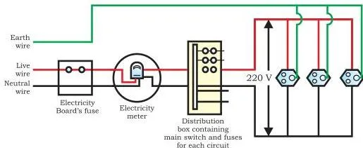
The last section turns the physics into the wiring behind a switchboard. The mains supply reaches the house through overhead poles or underground cables, and three wires do all the work (NCERT, p. 204):
- Live wire (red insulation) and neutral wire (black insulation) — the potential difference between them is 220 V.
- Earth wire (green insulation) — connected to a metal plate buried deep in the ground; it is a safety wire for appliances with metallic bodies, such as refrigerators, toasters and electric presses.
- House wiring is split into two circuits: 15 A for high-power appliances (geysers, air coolers) and 5 A for bulbs and fans. Appliances connect in parallel so each gets the same potential difference (p. 205), and each has its own switch.
The electric fuse protects the circuit. Its Joule heating melts it and breaks the circuit whenever the current climbs unduly high, preventing damage to appliances (p. 205). The chapter’s in-text question about a 2 kW oven on a 5 A, 220 V circuit is exactly this check: the oven demands more current than the circuit’s rating allows, so the fuse would blow.
Two faults trigger it. A short circuit occurs when the live and neutral wires come into direct contact (damaged insulation or a fault in an appliance), and the current rises abruptly. Overloading is different — too many appliances on a single socket, or an accidental hike in the supply voltage (p. 205).
Reading the chapter’s figures, in order
Every diagram in the chapter earns its place. Each figure below is the same one as in your book, with the thing to notice about it; follow them in order and the chapter’s argument builds itself.
The discovery: Oersted and the deflected needle (p. 195)
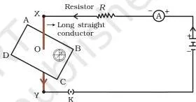
Hans Christian Oersted found in 1820 that a current-carrying wire deflects a nearby compass needle, and with that single observation connected electricity and magnetism. The circuit in Fig. 12.1 is Activity 12.1: a thick copper wire between points X and Y stands perpendicular to the page, a compass sits beside it, and when the key is inserted the needle swings.
Tracing the field: Fig. 12.3 and Fig. 12.4 (p. 197)
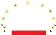
Fig. 12.3 shows the compass method of Activity 12.3: place the compass near the magnet, mark the needle’s two ends, then step the compass forward so its south pole occupies the old north-pole position; joining the marks traces one smooth field line.
Fig. 12.4 is the bar magnet’s full pattern — lines crowding at the poles, where the field is strongest, curving from north to south outside the magnet, with arrows always pointing the way a north pole would move.
Reversing the current: Fig. 12.5 (p. 198)
Fig. 12.5 shows Activity 12.4’s two arrangements side by side. With current flowing from north to south, the compass needle’s north pole moves east; with the cell connections swapped so current flows from south to north, the needle moves west. The two images together prove that the magnetic field’s direction reverses with the current.
The rule in one picture: Fig. 12.7 (p. 200)
Fig. 12.7 is the right-hand thumb rule itself: the thumb lies along the current, and the curled fingers show the circular field direction around the wire. Apply the same rule around a circular loop and you can work out the inside and outside directions asked in the section’s questions.
Loop and coil: Fig. 12.8 and Fig. 12.9 (pp. 200–201)
Fig. 12.8 shows the circular loop’s field: around each part of the wire the lines are still concentric circles, but they grow so large by the centre that they appear as straight lines — and every section of the wire contributes in the same direction inside the loop.
Fig. 12.9 is the iron-filings pattern of Activity 12.6 for a coil of many turns, the same picture with the field concentrated by extra turns.
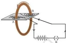
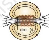
Solenoid and electromagnet: Fig. 12.10 and Fig. 12.11 (p. 201)
Fig. 12.10 is the solenoid’s field, and it should remind you of Fig. 12.4: parallel straight lines inside the coil mean a uniform field, and the outside lines loop from one end to the other, so the solenoid behaves like a bar magnet.
Fig. 12.11 shows what that strong inside field can do — magnetise a steel rod placed in the coil, forming an electromagnet.
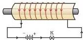
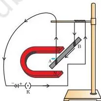
Force on the rod: Fig. 12.12 and Fig. 12.13 (pp. 202–203)
Fig. 12.12 is Activity 12.7: rod AB hangs between the poles of a horse-shoe magnet with the field directed upwards; current from B to A pushes the rod to the left, and reversing either the current or the field reverses the push. Fig. 12.13 shows Fleming’s left-hand rule — three mutually perpendicular fingers, with the thumb giving the force’s direction.
The house: Fig. 12.15 (p. 205)
Fig. 12.15 is a schematic of a common domestic circuit: live and neutral wires feed separate appliance circuits, each appliance has its own switch, and the earth wire runs alongside as the safety path. Notice how every appliance sits in parallel, so each receives the same 220 V.
Definitions at a glance
These are the vocabulary words the rules are written in; fix them before memorising the rules.
| Term | Plain meaning | NCERT page |
|---|---|---|
| Magnetic field | Region around a magnet (or a current-carrying wire) in which its force can be detected | p. 196 |
| Magnetic field lines | Curves that show the direction and strength of a magnetic field; closer lines mean a stronger field | p. 197 |
| Right-hand thumb rule | Thumb along the current; fingers curl in the field’s direction around the wire | p. 199 |
| Solenoid | Coil of many circular turns of insulated copper wire wound in the shape of a cylinder | p. 201 |
| Electromagnet | A magnetic material such as soft iron magnetised by the strong field inside a current-carrying coil | p. 201 |
| Fleming’s left-hand rule | Thumb = force, first finger = field, second finger = current; three fingers mutually perpendicular | p. 202 |
| Live, neutral, earth wires | Red live and black neutral carry the 220 V supply; green earth is a safety connection to the ground | p. 204 |
| Short circuit / overloading | Short circuit: live and neutral touch, current surges; overloading: too many appliances on one socket or a supply-voltage hike | p. 205 |
Common mistakes in this chapter, and the fix
Every mistake below is one the chapter itself warns about, or one its exercises deliberately test. Read the mistake, then the correction, then the check — the fastest way to stop losing marks on this chapter.
| Mistake | Correct rule | How to check your answer |
|---|---|---|
| Using the right-hand thumb rule to find the force on a wire in a field | The thumb rule gives the field around a current-carrying wire (p. 199); Fleming’s left-hand rule gives the force on a wire in a field (p. 202) | Ask what the question names: a wire carrying current alone → thumb rule; a wire inside a magnetic field → Fleming’s rule |
| Applying Fleming’s rule to electron flow as if it were the current | Use conventional current, which is opposite to the motion of electrons (p. 203) | If the question mentions electrons or an electron beam, reverse their direction first, then apply the rule |
| Drawing field lines that cross, or arrows pointing the wrong way inside the magnet | Lines never cross (p. 197); outside the magnet they run north to south, inside south to north, forming closed curves (p. 197) | Trace any line end to end — it must close on itself without meeting another line |
| Treating field lines as real physical paths | A field line is the path a hypothetical free north pole would take — a drawing tool, not a track (p. 206) | Remember the word “hypothetical”: no real particle rides along a field line |
| Reading the green wire as live | Red = live, black = neutral, green = earth (p. 204) | Exercise Q3(b) tests exactly this — green is earth, never live |
| Treating short circuit and overloading as the same fault | Short circuit = live and neutral in direct contact, current surges; overloading = too many appliances on one socket, or a supply-voltage hike (p. 205) | Name the cause: damaged insulation or direct contact → short circuit; too many plugs or a voltage rise → overloading |
Exam notes: what the exercises test
The chapter-end exercises repeat a small set of ideas; knowing which idea each question tests makes revision much faster. Worked Example 12.1 (the power line) and Example 12.2 (the electron in a field) show both hand rules in action (pp. 200, 203).
| Exercise question | Concept it tests |
|---|---|
| Q1 | Shape of the field near a long straight wire — concentric circles centred on the wire (option d, p. 207) |
| Q2 | Effect of a short circuit — the current increases heavily (option c) |
| Q3 | (a) the field at the centre of a long circular coil is parallel straight lines — true; (b) green insulation is the live wire — false, green is earth |
| Q4 | Two ways to produce a magnetic field — use a magnet, or pass current through a conductor |
| Q5 | The force on a conductor is largest when the current is at right angles to the magnetic field (p. 202) |
| Q6 | Fleming’s left-hand rule applied to an electron beam — conventional current is opposite to electron motion (p. 203) |
| Q7 | (i) right-hand thumb rule; (ii) Fleming’s left-hand rule; (iii) induced current — not developed in this chapter’s text |
| Q8 | Short circuit occurs when the live and neutral wires come into direct contact (p. 205) |
| Q9 | Earth wire gives leakage current a low-resistance path to the ground, keeping a metallic body at earth potential so the user does not get a severe shock (p. 204) |
Two answers need care. For Q7(iii), the chapter does not name a rule for induced current, so write only what the book’s text supports and do not introduce a rule the chapter never mentions. For Q6, reverse the electron’s direction to get the conventional current before applying Fleming’s rule.
A complete answer to any rule question names the rule, states which hand and which finger stands for what, and gives the direction in words.
The chapter’s one calculation is the fuse check, \(P = VI\). The book’s in-text question uses a 2 kW oven; here is the same idea with different numbers.
Step 1: Identify the data.
Power \(P = 3.5\ \text{kW} = 3500\ \text{W}\), supply voltage \(V = 220\ \text{V}\), fuse rating 5 A.
The power relation is \(P = VI\).
Step 2: Rearrange for current: \(I = \frac{P}{V}\).
Substitute the values:
\[ I = \frac{3500}{220} \approx 15.9\ \text{A} \]
Step 3: Compare with the fuse rating: \(15.9\ \text{A} \gt 5\ \text{A}\).
The appliance demands far more than the circuit allows.
Final answer: the 3.5 kW appliance draws about 15.9 A, well above the 5 A fuse rating, so the fuse melts and breaks the circuit. Such an appliance belongs on the 15 A circuit the chapter describes (p. 204).
Textbook contents and the examinable syllabus are not always identical — check the current official syllabus before deciding what to revise.
What you should have learnt from this chapter
These points are the chapter’s own closing summary, restated in short lines for the night before the exam (p. 206).
- A compass needle is a small bar magnet; the end that points north is the north pole.
- A magnetic field is the region around a magnet where its force can be detected.
- Field lines represent the field: closer lines mean a stronger field; a line is the path a hypothetical free north pole would take.
- A current-carrying wire produces a magnetic field; around a straight wire the lines are concentric circles, with direction given by the right-hand thumb rule.
- The field pattern depends on the conductor’s shape; a current-carrying solenoid behaves like a bar magnet.
- An electromagnet is a soft-iron core with a coil of insulated copper wire around it.
- A current-carrying conductor in a magnetic field experiences a force, largest when field and current are perpendicular; its direction is given by Fleming’s left-hand rule.
- Household supply is 220 V AC at 50 Hz, with live (red), neutral (black) and earth (green) wires.
- The fuse protects circuits against short circuit and overloading by melting from Joule heating and breaking the circuit.
Related resources
This listing is maintained for the 2026-27 academic session using the NCERT textbook information available to us. NCERT remains the authority for confirming the latest edition.
Continue with the next chapter, Our Environment, or step back to the previous chapter, Electricity, which explains the heating effect of current that the fuse relies on. For chapter-wise revision of this book, browse the Class 10 Science notes, collected alongside other subjects on the Class 10 notes hub, with the main notes index organising everything by class.
Reference: NCERT Class 10 Science textbook, chapter 12, official edition on ncert.nic.in.
Sources and data verification
- This page describes the NCERT Class 10 Science textbook, Chapter 12, “Magnetic Effects of Electric Current”, in the rationalised edition published by NCERT. The official chapter file is jesc112.pdf on ncert.nic.in, and the current edition can be verified on NCERT’s textbook portal.
- It covers the chapter’s own contents — sections, figures, activities and exercises — not the full CBSE subject scheme, which is larger.
- It is maintained for the current academic session using the NCERT information available to us.
- NCERT settles textbooks, editions and PDFs; CBSE settles curriculum, syllabus and examinations.
Frequently asked questions
Why does a compass needle get deflected when a current passes through a nearby wire?
A current-carrying wire produces a magnetic field around it — the discovery Oersted made in 1820 (p. 195). The compass needle is itself a small bar magnet (p. 196), so the wire’s field exerts a force on it and the needle turns. Reverse the current and the field reverses, so the needle deflects the other way (p. 198).
What is the difference between the right-hand thumb rule and Fleming’s left-hand rule?
The right-hand thumb rule gives the direction of the magnetic field around a current-carrying wire (p. 199). Fleming’s left-hand rule gives the direction of the force (motion) on a current-carrying conductor placed inside a magnetic field (p. 202). One finds a field; the other finds a force — that difference decides which rule to use.
Why is the magnetic field uniform inside a solenoid?
Inside a current-carrying solenoid the field lines are parallel straight lines (p. 201). Parallel, evenly spaced lines mean the field has the same magnitude and direction at every point inside — that is exactly what “uniform” means. This is why the section’s multiple-choice question has (d), “the same at all points”, as the correct answer.
What is the difference between a short circuit and overloading?
A short circuit happens when the live and neutral wires come into direct contact, usually through damaged insulation or a fault in an appliance, so the current increases abruptly (p. 205). Overloading is a different fault: too many appliances connected to a single socket, or an accidental hike in the supply voltage (p. 205).
Both melt the fuse, but their causes are different.
Why must appliances with metallic bodies be connected to an earth wire?
The earth wire gives any leakage current a low-resistance path to the ground, so the metallic body stays at earth potential (p. 204). Without it, a fault could leave the body at the live voltage, and a person touching it would receive a severe shock. That is why presses, toasters, refrigerators and similar appliances are earthed.
Which direction do magnetic field lines point inside a bar magnet?
Inside a bar magnet, field lines run from the south pole to the north pole. Outside, they run from north to south, which makes every field line a closed curve (p. 197). The arrow on a field line points in the direction a free north pole would move.
Explore Class 10 Science Books
Class 10 Science on LearnCBSE:
Related chapters:
- Chemical Reactions and Equations
- Acids, Bases and Salts
- Metals and Non-metals