Light – Reflection and Refraction Class 10 is Chapter 9 of the NCERT Class 10 Science textbook, running about 27 printed pages from page 133 to page 160.
The chapter splits into two halves — reflection by spherical mirrors, then refraction by spherical lenses. The official NCERT PDF is right below, followed by a section-by-section map, the formulas with their signs, and the mistakes students make here.
Download the Official NCERT PDF
The official file comes from NCERT’s own textbook page, so it matches the printed book exactly. Light – Reflection and Refraction Class 10 PDF (NCERT Science Chapter 9) opens the full chapter at print resolution with every figure and table, and the same page carries the entire Class 10 Science textbook if you need another chapter.
Chapter at a Glance
The chapter teaches two ways light changes direction. Reflection by spherical mirrors comes first and ends with the mirror formula; refraction then explains why light bends in water and glass, and leads to spherical lenses, the lens formula and the power of a lens.
The table below shows what the PDF contains, so you know how much of it there is before you open it.
| What the chapter holds | Count | Where it is used |
|---|---|---|
| Printed pages | 27 | |
| Sections in the chapter | 15 | |
| Figures with NCERT captions | 12 | |
| Tables | 5 | |
| Worked examples | 4 | solved step by step in our NCERT Solutions |
| Exercise questions | 17 | answered in our NCERT Solutions |
| In-text questions | 14 | |
| Activities | 13 | |
| Official NCERT PDF | Download the chapter PDF | the chapter exactly as NCERT publishes it |
What This Chapter Covers, Section by Section
This is the first of the two physics chapters in the book. The next chapter, The Human Eye and the Colourful World, builds directly on the lens ideas introduced here. The chapter divides into reflection with spherical mirrors (sections 9.1–9.2, roughly pages 134–145) and refraction with spherical lenses (section 9.3, roughly pages 145–160).
The two halves use the same two-ray logic and the same sign convention, which is why mirrors are taught first: master the concave mirror, and the lens half is mostly familiar arithmetic.
- Laws of reflection and the plane-mirror image (page 134)
- Spherical mirror terms and \( R = 2f \) (pages 135–136)
- Image formation by concave and convex mirrors, with Tables 9.1 and 9.2 (pages 137, 141)
- The rays you may trace in ray diagrams (pages 138–139)
- Uses of concave and convex mirrors (pages 140–142)
- New Cartesian sign convention (page 142)
- Mirror formula and magnification, with Examples 9.1 and 9.2 (pages 143–145)
- Everyday refraction and the two laws of refraction (pages 145–147)
- Refractive index, Table 9.3 and optical density (pages 148–149)
- Spherical lenses and their focus (pages 150–151)
- Image formation by lenses, with Tables 9.4 and 9.5 (pages 152–153)
- Lens ray diagrams, the lens formula, Examples 9.3 and 9.4 (pages 153–156)
- Power of a lens in dioptres (page 157)
- The chapter’s own summary and the closing exercises (pages 158–160)
The chapter is built around simple home experiments: a shining spoon as a curved mirror, sunlight burning paper at the focus of a concave mirror, a coin that reappears when water is poured into a bowl. Each activity previews one idea before the book formalises it.
Key Concepts: What Each Idea Means and Why It Works
This chapter is about where light goes when it reaches something. A polished surface bounces light back — that is reflection. A transparent surface bends light because the light changes speed there — that is refraction. Everything that follows is two formulas with one sign convention.
Spherical Mirrors: Pole, Focus and R = 2f
A spherical mirror is a slice of the inside or outside of a hollow sphere, polished so it reflects. This section names the parts of that slice and gives the one relationship, \( R = 2f \), that every mirror numerical starts from.
Terms first (pages 135–136):
- Pole P — the centre of the reflecting surface; it lies on the mirror.
- Centre of curvature C — the centre of the sphere the mirror is a part of. It is not on the mirror: in front for a concave mirror, behind for a convex mirror.
- Radius of curvature R — the radius of that sphere; the distance PC equals R.
- Principal axis — the straight line through P and C; it is normal to the mirror at the pole.
- Principal focus F — where rays parallel to the axis actually meet after reflection (concave) or appear to come from (convex).
- Focal length f — the distance from the pole to the focus.
- Aperture — the diameter of the reflecting surface.
For any spherical mirror of small aperture, \( R = 2f \) (page 136). That is why the principal focus lies midway between the pole and the centre of curvature.
Activity 9.2 gives a working definition of the focus (page 136). Sunlight, which arrives parallel to the axis, is converged by a concave mirror to a bright spot that burns paper. That spot is a tiny real, inverted image of the Sun, and its distance from the mirror gives the approximate focal length.
| Mirror | Use | Reason given by NCERT |
|---|---|---|
| Concave | Torches, searchlights, vehicle headlights | Produces a powerful parallel beam of light (page 140). |
| Concave | Shaving mirrors, dentist’s mirror | Gives a larger, erect image of the face or teeth (page 140). |
| Concave | Solar furnace | A large concave mirror concentrates sunlight to produce heat (page 140). |
| Convex | Rear-view mirror in vehicles | Always erect though diminished, with a wider field of view because the surface curves outward (page 142). |
Activity 9.6 shows the same convex-mirror advantage on a large scale: a small convex mirror can show the full image of a tall building — as at Agra Fort, where one is fitted facing the Taj Mahal (page 141).
The Sign Convention, Mirror Formula and Magnification
The same concave mirror can give a real or a virtual image, enlarged or diminished. The New Cartesian sign convention is how the formula knows which case it is solving: it turns a word problem into signed numbers.
The five rules (page 142):
- The object is always placed to the left of the mirror, so light falls on the mirror from the left.
- All distances parallel to the principal axis are measured from the pole.
- Distances to the right of the origin are positive; to the left, negative.
- Distances above the principal axis are positive.
- Distances below the principal axis are negative.
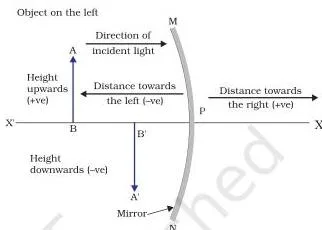
The convention exists so that one formula serves every case: the signs of v and f carry the real-virtual information, so no separate equation is needed for a virtual image.
Mirror formula (page 143): \( \frac{1}{v} + \frac{1}{u} = \frac{1}{f} \), where u is the object distance, v the image distance and f the focal length. The formula is valid for all spherical mirrors and all object positions, but you must apply the sign convention before substituting numbers — the book insists on this before solving.
Magnification (page 143): \( m = \frac{h’}{h} = -\frac{v}{u} \). Object height h is taken positive; image height h’ is positive for a virtual image and negative for a real image. So a negative m means real and inverted, a positive m means virtual and erect.
NCERT works the convention through Example 9.1 (a convex mirror, page 144) and Example 9.2 (a concave mirror, pages 144–145). Two original worked examples with the same method appear in the exam notes section below.
Refraction: Laws, Refractive Index and Optical Density
The raised bottom of a pond, the pencil that looks bent in a glass of water, and the coin that reappears when water is poured into a bowl are all the same event: light changes speed when it enters a new medium, and a change of speed with a change of direction is refraction (pages 145–146).
The two laws of refraction (page 147):
- The incident ray, the refracted ray and the normal at the point of incidence all lie in the same plane.
- \( \frac{\sin i}{\sin r} \) is a constant for light of a given colour and a given pair of media — Snell’s law — true for \( 0 \lt i \lt 90^\circ \).
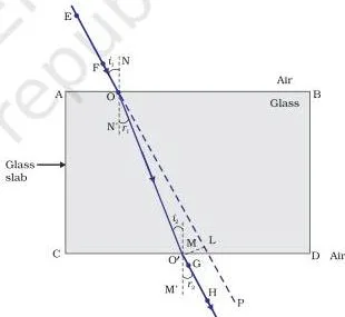
Read the glass-slab diagram ray by ray (page 147). The ray bends toward the normal entering glass from air, and away from the normal leaving glass into air. Because the two faces are parallel, the two bends are equal and opposite, so the emergent ray is parallel to the incident ray but shifted sideways.
This sideward shift is why letters under a glass slab look raised.
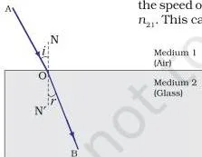
The refractive index measures how much the speed changes (page 148). If light travels from medium 1 to medium 2, \( n_{21} = \frac{v_1}{v_2} \). When medium 1 is vacuum or air, this becomes the absolute refractive index \( n = \frac{c}{v} \), where \( c = 3 \times 10^{8}\ \text{m/s} \) is the speed of light in vacuum.
Three reference values from Table 9.3 (page 149): water 1.33, crown glass 1.52, diamond 2.42. The book says you need not memorise the table.
Optical density is not mass density. The chapter’s own counter-example: kerosene has a higher refractive index (1.44) than water (1.33), so kerosene is optically denser, even though its mass density is lower than water’s (page 149). Optically denser simply means the larger refractive index; light travels slower there and bends toward the normal when entering it.
Lenses: Focus, Lens Formula, Magnification and Power
A magnifying glass is a lens — a transparent material that bends light twice, once on entering and once on leaving. This section shows that two carefully chosen bends can form an image just as a mirror does.
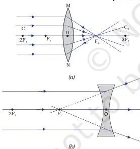
Definitions (pages 150–151): a lens is a transparent material bound by two surfaces, at least one of them spherical. A convex lens is thicker in the middle and converges light, so it is also called a converging lens; a concave lens is thicker at the edges and diverges light, so it is also called a diverging lens.
A lens has two centres of curvature, C1 and C2, one for each spherical surface. The line through both is the principal axis, and the central point O is the optical centre — a ray through O passes without deviation.
The lens also has two principal foci, F1 and F2, and its focal length f is the distance from the optical centre to a focus. The aperture is the effective diameter of the circular outline (pages 150–151).
Parallel rays are the quickest test of a lens (page 151). A convex lens converges them to a real focus; a concave lens makes them appear to diverge from a virtual focus.
Activity 9.11 measures a convex lens’s focal length the same way the mirror’s was measured: sunlight burns paper at the sharp spot, and the lens-to-spot distance is the approximate focal length.
The one-sentence rule for concave lenses (page 153): a concave lens always forms a virtual, erect and diminished image, whatever the object position, so it can never throw an image on a screen.
Lens formula (page 155): \( \frac{1}{v} – \frac{1}{u} = \frac{1}{f} \), with distances measured from the optical centre. Focal length is positive for a convex lens and negative for a concave lens. Signs must be applied before substituting, exactly as with mirrors.
Magnification by a lens (page 156): \( m = \frac{h’}{h} = \frac{v}{u} \) — note there is no minus sign, unlike the mirror version.
Power of a lens (page 157): \( P = \frac{1}{f} \), with f in metres, giving the unit dioptre (D), where \( 1\ \text{D} = 1\ \text{m}^{-1} \). Convex lenses have positive power, concave lenses negative. Lenses placed in contact combine by the algebraic sum of their powers.
Figure Walkthrough: Reading the Ray Diagrams
The ray diagrams in this chapter are the working, not illustrations. Every image position in Tables 9.1, 9.2, 9.4 and 9.5 is the spot where two reflected or refracted rays cross, so learning to read the diagrams saves memorising the tables.
Fig 9.1, Fig 9.2 and Fig 9.3: Mirror Shapes, the Focus and the Three Rays
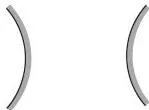
Fig 9.1 (page 135) shows the two mirror shapes with their backs shaded. The reflecting surface is the unshaded curve — inward for the concave mirror, outward for the convex. The same idea sits on your kitchen spoon: the inward face behaves like a concave mirror, the bulged face like a convex one (Activity 9.1, page 135).
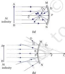
Fig 9.2 (page 136) answers the question that decides the whole chapter: what happens to rays parallel to the principal axis? The concave mirror reflects them so they actually meet at F. The convex mirror reflects them so they spread apart; they only appear to come from F behind the mirror.
That difference is exactly why a concave mirror can form a real image and a convex mirror cannot. The aperture is the diameter MN.
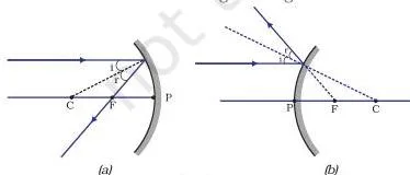
Fig 9.3 (page 138) shows the three rays you are allowed to trace. A ray parallel to the axis goes through F after reflection (or appears to come from F). A ray through F emerges parallel to the axis. A ray through C is reflected back along itself, because it strikes the mirror along the normal.
Any two of these rays locate the image — the book says the intersection of at least two reflected rays gives the image position.
Fig 9.7 and Fig 9.8: Ray Diagrams for Concave and Convex Mirrors
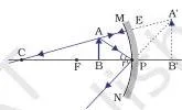
Fig 9.7 (pages 139–140) walks the concave mirror through the rows of Table 9.1. Object beyond C: real image between F and C, diminished. Object at C: image at C, same size. Object between C and F: image beyond C, enlarged.
Object at F: the reflected rays come out parallel, so the table honestly says the image would not be formed — it is at infinity. Object between P and F: the reflected rays never meet in front, so you extend them behind the mirror; this is the one virtual, erect, enlarged case, and it is why a shaving mirror works.
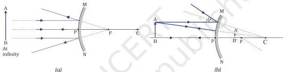
Fig 9.8 (page 141) has only two cases to show, matching Table 9.2. Object at infinity: point-sized image at F behind the mirror. Object anywhere else: diminished, erect image between P and F. Every convex-mirror image is virtual — the reason the rear-view mirror always shows an erect view of the traffic behind.
Fig 9.16 and Fig 9.17: Ray Diagrams for Convex and Concave Lenses
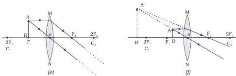
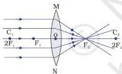
Fig 9.16 (pages 154–155) repeats the mirror logic with three lens rays: a ray parallel to the axis goes through F2 after the lens; a ray through F1 emerges parallel; a ray through the optical centre passes straight.
Against Table 9.4 (page 152): object beyond 2F1 gives a real, diminished image between F2 and 2F2; object at 2F1 gives a same-size real image at 2F2; object between F1 and the optical centre gives an enlarged, virtual, erect image on the same side — the magnifying glass.
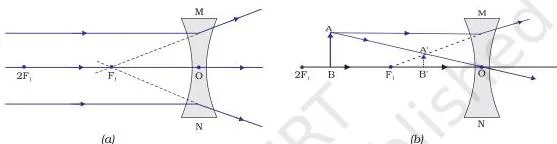
Fig 9.17 (page 155) has no variety, and that is the point: whatever the object position, a concave lens gives a virtual, erect, diminished image between F1 and the optical centre. Table 9.5 (page 153) needs only two rows for the same reason.
The idea the book wants you to carry is that a concave lens never forms a real image, so it can never cast one on a screen.
Definitions: The Terms You Should Be Able to Write
Numericals are only half the chapter. The other half is writing what these terms mean, and most are defined by the book in a single sentence. The table below gives each term in exam-ready words, with the page where the book defines it.
| Term | Definition |
|---|---|
| Pole | The centre of the reflecting surface of a spherical mirror; it lies on the surface of the mirror (page 135). |
| Centre of curvature | The centre of the sphere of which the mirror’s reflecting surface forms a part; it is not part of the mirror (page 135). |
| Radius of curvature | The radius of that sphere; the distance from the pole to the centre of curvature (page 135). |
| Principal focus of a concave mirror | The point on the principal axis where rays parallel to the axis actually meet after reflection (page 136). |
| Principal focus of a convex mirror | The point on the principal axis from which rays parallel to the axis appear to come after reflection (page 136). |
| Focal length | The distance between the pole and the principal focus of a spherical mirror (page 136). |
| Aperture | The diameter of the reflecting surface of a spherical mirror (page 136). |
| Magnification | The ratio of the height of the image to the height of the object (page 143). |
| Refractive index | The ratio of the speed of light in medium 1 to the speed of light in medium 2, for a given pair of media (page 148). |
| Absolute refractive index | The refractive index of a medium with respect to vacuum or air; \( n = c/v \) (pages 148–149). |
| Optically denser medium | Of two media, the one with the larger refractive index (page 149). |
| Principal focus of a lens | The point on the principal axis where rays parallel to the axis converge (convex lens) or appear to diverge from (concave lens) after refraction (page 151). |
| Optical centre | The central point of a lens; a ray passing through it suffers no deviation (page 150). |
| Power of a lens | The reciprocal of its focal length, \( P = 1/f \) (page 157). |
| Dioptre | The SI unit of power of a lens; 1 dioptre is the power of a lens of focal length 1 metre, so \( 1\ \text{D} = 1\ \text{m}^{-1} \) (page 157). |
Two definitions the book asks for directly in its in-text questions are the principal focus of a concave mirror (page 142) and 1 dioptre of power (page 158). Practise both in your own words.
Common Mistakes in This Chapter (And the Correction)
Most marks lost in this chapter are lost on habits, not difficulty: wrong signs, swapped formulas, and mistaking optical density for mass density. Each mistake below comes with the page that proves the correction.
| Mistake | Correct rule | How to check your answer |
|---|---|---|
| Substituting u, v and f without applying the sign convention. | Apply New Cartesian signs before solving: distances opposite to the incident light are negative, and concave mirror and concave lens focal lengths are negative (pages 142–143, 155). | Put your v back into the formula. If both sides of the equation balance, the signs were right. |
| Mixing up the mirror formula and the lens formula. | Mirror: \( \frac{1}{v} + \frac{1}{u} = \frac{1}{f} \) (page 143). Lens: \( \frac{1}{v} – \frac{1}{u} = \frac{1}{f} \) (page 155). | Name the device before writing the formula: mirrors add reciprocals, lenses subtract. |
| Calling kerosene optically rarer than water because it is lighter. | Optical density means larger refractive index, nothing else. Kerosene (1.44) is optically denser than water (1.33) though its mass density is lower (page 149). | Compare refractive index values, never mass density. |
| Expecting a concave lens to form a real image. | A concave lens always gives a virtual, erect, diminished image whatever the object position (page 153). | If a concave-lens calculation puts v on the far side with a positive sign, recheck: virtual images are on the object’s side. |
| Reading a negative magnification as “smaller”. | The sign of m tells real/inverted (negative) versus virtual/erect (positive); the magnitude tells relative size (pages 143, 156). | State nature and size separately: “real and inverted, twice the size”. |
| Assuming a half-covered convex lens gives half an image. | A complete image still forms: rays from each object point reach every part of the lens, so the uncovered half alone forms the whole image, just dimmer (page 159). | Trace two rays through the uncovered half — they still cross at the full image position. |
Exam Notes: A Working Method for the Numericals
Every numerical in this chapter is the same task: turn a sentence into signed distances, put them in one formula, solve, and translate the sign of the answer back into words.
- List with signs. Write u, v, f, R, h and h’ with their correct signs; when R is given, find f first with \( f = R/2 \). The sign of f is fixed by the device: negative for a concave mirror or concave lens, positive for a convex mirror or convex lens.
- Choose the formula. Mirror: \( \frac{1}{v} + \frac{1}{u} = \frac{1}{f} \). Lens: \( \frac{1}{v} – \frac{1}{u} = \frac{1}{f} \).
- Do the reciprocal arithmetic slowly. Rearrange to isolate \( 1/v \), combine the fractions, then invert at the end. This is where slips happen.
- Interpret the signs. The sign of v gives the side of the image; the sign of m or h’ gives real/inverted versus virtual/erect; the magnitude of m gives the size.
Worked Example 1: Concave Mirror
Step 1: An object 2.0 cm tall is placed 18 cm in front of a concave mirror of focal length 12 cm.
Concave mirror: \( f = -12\ \text{cm} \).
Object in front: \( u = -18\ \text{cm} \).
Object height \( h = +2.0\ \text{cm} \).
- Step 1: Use the mirror formula \( \frac{1}{v} + \frac{1}{u} = \frac{1}{f} \).
- Step 2: Substitute the signed values:
\[ \frac{1}{v} = \frac{1}{f} – \frac{1}{u} = \frac{1}{-12} – \frac{1}{-18} = -\frac{1}{12} + \frac{1}{18} \]
\[ \frac{1}{v} = \frac{-3 + 2}{36} = -\frac{1}{36} \quad \Rightarrow \quad v = -36\ \text{cm} \]
Step 4: Magnification \( m = -\frac{v}{u} = -\frac{(-36)}{(-18)} = -2 \), so \( h’ = mh = (-2)(2.0) = -4.0\ \text{cm} \).
Final answer: The image is real and inverted, 4.0 cm tall, formed 36 cm in front of the mirror, twice the size of the object.
Worked Example 2: Convex Lens Used as a Magnifier
Step 1: A convex lens of focal length 8 cm is used as a magnifying glass.
The object is placed 5 cm from the lens.
Convex lens: \( f = +8\ \text{cm} \).
Object on the left: \( u = -5\ \text{cm} \).
- Step 1: Use the lens formula \( \frac{1}{v} – \frac{1}{u} = \frac{1}{f} \).
- Step 2: Rearrange and substitute:
\[ \frac{1}{v} = \frac{1}{f} + \frac{1}{u} = \frac{1}{8} + \frac{1}{-5} = \frac{1}{8} – \frac{1}{5} \]
\[ \frac{1}{v} = \frac{5 – 8}{40} = -\frac{3}{40} \quad \Rightarrow \quad v = -\frac{40}{3} = -13.3\ \text{cm} \]
Step 4: Magnification \( m = \frac{v}{u} = \frac{-40/3}{-5} = \frac{8}{3} \approx +2.67 \).
Final answer: The image is virtual and erect, 13.3 cm from the lens on the same side as the object, enlarged 2.67 times.
Which Exercise Tests Which Idea
The closing exercises run from page 158 to page 160. Use this map to target your revision by formula rather than solving them in order.
| Exercises | Idea tested | Where the idea lives |
|---|---|---|
| 1–6 | Concept-choice: materials for a lens; the concave-mirror position for a virtual enlarged image; same-size real image by a convex lens; meaning of a negative focal length; mirrors that keep an image erect; the lens for reading a dictionary. | Tables 9.1, 9.2, 9.4, 9.5 (pages 137, 141, 152–153) |
| 7 | Erect image from a concave mirror: object between P and F, enlarged, with a ray diagram. | Table 9.1, last row (page 137); Fig 9.7 |
| 8 | Naming concave and convex mirror uses with reasons. | Uses paragraphs (pages 140, 142) |
| 9 | Half-covered convex lens: full but dimmer image, verified experimentally. | Exercise 9 (page 159) |
| 10–11 | Lens formula numericals: convex lens (real image) and concave lens (virtual image). | Pages 155–156 |
| 12, 14, 15 | Mirror formula numericals: convex mirror twice, concave mirror once. | Pages 143–145 |
| 13 | Meaning of magnification +1: same size, erect. | Pages 143, 156 |
| 16–17 | Power of a lens: focal length from power, converging or diverging lens. | Page 157 |
A complete numerical answer states position, size and nature separately, each with its unit. The reasoning questions (7, 8, 9) expect a ray diagram or a named reason drawn from the book’s tables. Textbook contents and the examinable syllabus are not always identical, so check the current official CBSE syllabus for what is examinable this session.
Revision Summary: The Chapter in One Page
NCERT closes the chapter with its own summary on page 158. This is that list retold in plainer words — a five-minute revision pass before the exam.
- Light seems to travel in straight lines; a small source casts a sharp shadow (page 133).
- All reflecting surfaces obey the laws of reflection; all refracting surfaces obey the laws of refraction.
- For small-aperture spherical mirrors, \( R = 2f \), so F lies midway between P and C (pages 135–136).
- Mirror formula: \( \frac{1}{v} + \frac{1}{u} = \frac{1}{f} \); magnification is \( h’/h \) (page 143).
- Light bends toward the normal when it slows into a denser medium, and away from the normal when it speeds into a rarer one (page 149).
- Light travels at \( 3 \times 10^{8}\ \text{m/s} \) in vacuum and slower in every medium; refractive index is the ratio of the speed in vacuum or air to the speed in the medium (page 148).
- Through a rectangular glass slab the emergent ray is parallel to the incident ray but shifted sideways (page 147).
- Lens formula: \( \frac{1}{v} – \frac{1}{u} = \frac{1}{f} \) (page 155).
- Power of a lens is the reciprocal of its focal length, in dioptres, positive for convex and negative for concave (page 157).
The table below collects every formula of the chapter with the meaning of each symbol — the part to revise from the night before.
| Formula | What it relates | Symbols and units |
|---|---|---|
| \( \frac{1}{v} + \frac{1}{u} = \frac{1}{f} \) (mirror formula, page 143) | Object distance, image distance and focal length of a spherical mirror | u, v, f measured from the pole, all in the same length unit; u and v negative for a real object and a real image on the left |
| \( m = \frac{h’}{h} = -\frac{v}{u} \) (page 143) | Image size and position to object size | h positive above the axis; h’ positive for virtual, negative for real; m has no unit |
| \( \frac{\sin i}{\sin r} = n \) (Snell’s law, page 148) | Angles of incidence and refraction | i and r are angles with the normal; n is the refractive index of the second medium with respect to the first |
| \( n = \frac{c}{v} \) (page 149) | Speed of light in a medium | c = \( 3 \times 10^{8}\ \text{m/s} \) in vacuum or air; v is the speed in the medium; n has no unit |
| \( \frac{1}{v} – \frac{1}{u} = \frac{1}{f} \) (lens formula, page 155) | Object distance, image distance and focal length of a spherical lens | u, v, f measured from the optical centre; f positive for convex, negative for concave |
| \( m = \frac{h’}{h} = \frac{v}{u} \) (page 156) | Image size and position to object size for a lens | No minus sign, unlike the mirror version |
| \( P = \frac{1}{f} \) (page 157) | Focal length to power of a lens | f in metres; P in dioptres; \( 1\ \text{D} = 1\ \text{m}^{-1} \); convex positive, concave negative |
Related Resources
This listing is maintained for the 2026-27 academic session using the NCERT textbook information available to us. NCERT remains the authority for confirming the latest edition.
Continue with the chapters around this one, or step back to the hub pages:
- Class 10 Science notes — all chapters of the NCERT Science book in one place.
- Class 10 hub — notes for all Class 10 subjects.
- Heredity (Chapter 8) — the chapter that comes before this one.
- The Human Eye and the Colourful World (Chapter 10) — the next chapter, which builds on these lens ideas.
- CBSE notes home — the starting point for every class and subject.
Reference: NCERT Class 10 Science textbook, chapter 9, official edition on ncert.nic.in.
Sources and Data Verification
- The sections, figures, formulas and page numbers on this page describe Chapter 9, Light – Reflection and Refraction, of the NCERT Class 10 Science textbook, official edition on ncert.nic.in.
- This page covers Chapter 9 only; the other chapters of the book are not described here.
- The page is maintained for the current academic session using the NCERT information available to us. Textbook contents and the examinable syllabus are not always identical, so the current official syllabus should be checked.
- NCERT settles textbooks, editions and PDFs; CBSE settles curriculum, syllabus and examinations.
FAQs on Light – Reflection and Refraction Class 10
Why do we prefer a convex mirror as a rear-view mirror in vehicles?
A convex mirror always gives an erect, though diminished, image, and because it curves outward it has a wider field of view, so the driver sees a much larger area than a plane mirror would show (page 142). The smaller image is a fair trade for seeing the whole traffic behind.
When does a concave mirror form a virtual, erect and enlarged image?
When the object is placed between the pole P and the principal focus F of the mirror (Table 9.1, page 137). The reflected rays never meet in front of the mirror, so the image forms behind it, virtual and enlarged — the shaving-mirror case.
Will a convex lens still form a complete image if half of it is covered with black paper?
Yes — a complete image still forms, but it is dimmer (Exercise 9, page 159). Rays from each point of the object reach every part of the lens, so the uncovered half alone is enough to converge rays to every image point; covering half only reduces the light passing through.
What is the difference between the mirror formula and the lens formula?
The mirror formula is \( \frac{1}{v} + \frac{1}{u} = \frac{1}{f} \) (page 143) and the lens formula is \( \frac{1}{v} – \frac{1}{u} = \frac{1}{f} \) (page 155) — the same three symbols, but the sign between the two terms differs.
The reason is geometric: a mirror reflects light back, so a real image lies on the same side as the object and both distances carry the same sign; a lens transmits light forward, so a real image lies on the opposite side, and the minus sign covers that.
For lenses, distances are measured from the optical centre; for mirrors, from the pole.
Why does a pencil partly immersed in water appear to be displaced at the surface?
Because of refraction at the air-water interface (pages 145–146). Light from the underwater part of the pencil changes direction as it leaves the water, so it reaches your eye as if it came from a higher position — the submerged part looks raised and the pencil looks bent or displaced at the surface.
The same reason makes the bottom of a pond look raised.
What does it mean that the refractive index of diamond is 2.42?
It means light travels 2.42 times faster in air than in diamond (pages 148–149). Since \( n = c/v \), the speed of light in diamond is \( 3 \times 10^{8} / 2.42 \approx 1.24 \times 10^{8}\ \text{m/s} \). A higher refractive index also means diamond is optically denser and bends light more sharply.
Reference: NCERT Class 10 Science textbook, chapter 9, official edition on ncert.nic.in.
Explore Class 10 Science Books
Class 10 Science on LearnCBSE:
Related chapters:
- Chemical Reactions and Equations
- Acids, Bases and Salts
- Metals and Non-metals