This page is for Electricity Class 10 — Chapter 11 of the NCERT Science textbook. The chapter runs 24 printed pages, from book page 171 to page 194.
It explains what electric current is, what makes it flow, how resistors combine, and what happens to the energy the current carries. The official NCERT chapter PDF is right below; the rest of the page explains what is inside it.
Download the Electricity Class 10 Science Chapter 11 PDF
This is the official NCERT file for the chapter, hosted on ncert.nic.in — the same PDF distributed as the eleventh chapter of the Class 10 Science book.
Open the Electricity Class 10 Science Chapter 11 PDF to read the full chapter exactly as published, including every figure, activity and worked example across book pages 171 to 194, and keep it open while you work through this page.
| What the chapter holds | Count | Where it is used |
|---|---|---|
| Printed pages | 24 | |
| Sections in the chapter | 11 | |
| Figures with NCERT captions | 10 | |
| Tables | 4 | |
| Worked examples | 13 | solved step by step in our NCERT Solutions |
| Exercise questions | 18 | answered in our NCERT Solutions |
| In-text questions | 23 | |
| Activities | 6 | |
| Official NCERT PDF | Download the chapter PDF | the chapter exactly as NCERT publishes it |
Reference: NCERT Class 10 Science textbook, chapter 11, official edition on ncert.nic.in.
Electricity Class 10: Chapter at a Glance
The table below lists what the chapter holds in this edition — sections, figures, activities, worked examples and exercise questions — so you know what you are getting before you open the file.
What Is Inside Electricity Class 10 Chapter 11
The chapter moves in a straight line: first it defines current and voltage, then it joins them with Ohm’s law, then it combines resistors, and finally it follows the energy from current into heat and power. Knowing where each idea lives makes the book easier to follow.
- 11.1 Electric current and circuit (p. 171): what an electric current is, the ampere, and why a closed circuit is needed for current to flow.
- 11.2 Electric potential and potential difference (p. 173): what pushes charge to move, the volt, and how a voltmeter is connected.
- 11.3 Circuit diagram (p. 174): the standard symbols of Table 11.1 — cell, battery, switch, bulb, resistor, rheostat, ammeter and voltmeter — used to draw circuits.
- 11.4 Ohm’s law (p. 175): the V-I relationship for a metallic wire, resistance, the ohm, and the rheostat as a variable resistance.
- Factors on which resistance depends (p. 177-178): length, area of cross-section and material, with resistivity and Table 11.2.
- 11.6 Resistance of a system of resistors (p. 181): equivalent resistance of series and parallel combinations.
- 11.7 Heating effect of electric current (p. 188): why a resistor gets hot, \( H = VIt \) and Joule’s law.
- Practical applications of heating (p. 190): tungsten filaments and the electric fuse.
- 11.8 Electric power (p. 191): the watt, the kilowatt, and the commercial unit kilowatt hour.
- What you have learnt (p. 192): the chapter’s own closing summary, useful as a revision checklist.
- Exercises (p. 193): the end-of-chapter problem set, from multiple choice to reasoning.
Electricity Class 10: Key Concepts Explained
The chapter answers three questions: what makes charge flow, what controls how much flows, and what happens to the energy the flow carries. Each block below gives one idea, with the formula and the NCERT page.
Electric Current and the Ampere
Current is the rate at which charge passes a point — like the amount of water that goes past a spot in a river each second. If a net charge \( Q \) crosses a cross-section in time \( t \), the current is \[ I = \frac{Q}{t} \quad \text{(Eq. 11.1, p. 172)} \]
The SI unit is the ampere (A): \( 1\ \text{A} = 1\ \text{C/s} \). One coulomb is the charge of roughly \( 6 \times 10^{18} \) electrons, and smaller currents are written in milliampere (\( 1\ \text{mA} = 10^{-3}\ \text{A} \)) or microampere (\( 1\ \mu\text{A} = 10^{-6}\ \text{A} \)).
Electrons carry charge in wires, but current was defined before electrons were known, so the conventional direction of current is opposite to the flow of electrons (p. 172). An ammeter measures current and is connected in series, in the path the current takes.
Watch the time unit: in \( I = Q/t \), time must be in seconds. Example 11.1 converts 10 minutes to 600 s before substituting (p. 172).
Potential Difference and the Volt
Charge does not move by itself. Like water in a horizontal tube, electrons in a wire stay put unless something pushes them — and that push is a difference of electric pressure called potential difference (p. 173). A cell or battery produces it by chemical action and maintains it across its terminals.
Potential difference \( V \) between two points is the work \( W \) done to move a unit charge \( Q \) from one point to the other:
\[ V = \frac{W}{Q} \quad \text{(Eq. 11.2, p. 173)} \]
One volt is the potential difference that moves one coulomb with one joule of work: \( 1\ \text{V} = 1\ \text{J/C} \). A voltmeter measures potential difference and is always connected in parallel across the two points (p. 173).
Ohm’s Law and Resistance
Ohm’s law is the single relationship between current, voltage and resistance, and nearly every numerical in the chapter applies it. For a metallic wire, \( V/I \) stays constant, so the V-I graph is a straight line through the origin (Fig. 11.3, p. 175-176).
In words: the potential difference across the ends of a metallic wire is directly proportional to the current through it, provided its temperature remains the same. That gives \[ R = \frac{V}{I} \quad \text{(Eq. 11.6, p. 176)} \qquad I = \frac{V}{R} \quad \text{(Eq. 11.7, p. 176)} \]
The constant \( R \) is the resistance — the property of a conductor that resists the flow of charge — measured in ohms, where \( 1\ \Omega = 1\ \text{V/A} \).
The temperature condition is part of the law itself: if the wire heats up, the straight line bends. A rheostat is a variable resistance used to regulate current without changing the voltage source (p. 176).
Resistivity and the Factors That Change Resistance
A wire’s resistance is not fixed by the metal alone. Activity 11.3 shows three findings: doubling a wire’s length halves the current, a thicker wire of the same material lets more current through, and changing the material changes the current (p. 177-178).
So resistance is directly proportional to length \( l \) and inversely proportional to area of cross-section \( A \):
\[ R = \rho \frac{l}{A} \quad \text{(Eq. 11.10, p. 178)} \]
Resistivity \( \rho \) (rho) is the material’s own characteristic property, independent of the wire’s size, with unit ohm metre. Both resistance and resistivity change with temperature (p. 178).
Table 11.2 puts conductors near \( 10^{-8}\ \Omega\,\text{m} \) and insulators like glass and rubber between \( 10^{12} \) and \( 10^{17}\ \Omega\,\text{m} \). Alloys generally have higher resistivity than their constituent metals and do not oxidise readily at high temperatures — which is why they are used in electric irons and toasters. Tungsten is used for bulb filaments, and copper and aluminium for transmission lines (p. 178).
The book notes under Table 11.2 that the values need not be memorised — they are there for solving numerical problems. The ones that recur are copper at \( 1.6 \times 10^{-8}\ \Omega\,\text{m} \), used in Exercise Q6, and nichrome, which appears throughout the activities. The useful habit is to check whether a material sits in the conductor range or the insulator range.
Series and Parallel Circuits
Most circuits contain more than one resistor, and the two ways of joining them behave in opposite ways — a point students routinely reverse. Series resistors are joined end to end in a single path (Fig. 11.6, p. 181); parallel resistors are connected between the same two points, making separate branches (Fig. 11.7, p. 182).
In series, the same current flows through every resistor and the total voltage is the sum of the individual voltages (Activity 11.5, p. 183). Applying Ohm’s law gives the equivalent resistance \[ R_s = R_1 + R_2 + R_3 \quad \text{(Eq. 11.14, p. 184)} \]
so the combination is larger than any single resistance. In parallel, every branch sees the same voltage and the total current is the sum of the branch currents:
\[ \frac{1}{R_p} = \frac{1}{R_1} + \frac{1}{R_2} + \frac{1}{R_3} \quad \text{(Eq. 11.18, p. 186)} \]
so the equivalent resistance is smaller than the smallest branch resistance. The book’s own examples show why this matters: fairy lights stop working when one bulb fails because series breaks the whole circuit, while household devices need parallel wiring because each appliance draws its own current (p. 187).
| Property | Series circuit | Parallel circuit |
|---|---|---|
| How resistors are joined | end to end, one single path (p. 181) | between the same two points, separate branches (p. 182) |
| Current | same through every resistor | divides among branches: \( I = I_1 + I_2 + I_3 \) |
| Voltage | divides: \( V = V_1 + V_2 + V_3 \) | same across every branch |
| Equivalent resistance | \( R_s = R_1 + R_2 + R_3 \), larger than any one (p. 184) | \( \frac{1}{R_p} = \frac{1}{R_1} + \frac{1}{R_2} + \frac{1}{R_3} \), smaller than the smallest (p. 186) |
| If one component fails | the whole circuit breaks (fairy lights, p. 187) | other branches keep working |
| Practical use | not used for domestic wiring | used for home appliances (p. 187) |
Heating Effect and Joule’s Law
When current flows through a resistor, the energy supplied by the source turns into heat — that is why a fan warms up after long use, and why heaters and irons exist. In a purely resistive circuit, all the source energy is dissipated as heat (p. 188).
Moving a charge \( Q \) through a potential difference \( V \) needs work \( VQ \), so for a steady current the heat produced is \[ H = VIt \quad \text{(Eq. 11.20, p. 188)} \]
Using Ohm’s law, this becomes Joule’s law of heating:
\[ H = I^2 R t \quad \text{(Eq. 11.21, p. 189)} \]
The law says heat is proportional to the square of the current, directly to the resistance, and directly to the time. Doubling the current therefore quadruples the heat.
Applications: tungsten (melting point \( 3380^\circ\text{C} \)) is used for bulb filaments, and bulbs are filled with nitrogen and argon to protect the filament (p. 190). A fuse — a wire of chosen melting point placed in series — melts and breaks the circuit when the current exceeds its rating; domestic fuses are rated like 1 A, 2 A, 5 A and 10 A (p. 190).
Electric Power and the Kilowatt Hour
Electric power is the rate at which the circuit consumes energy — the number that decides how fast the electricity metre runs. It is given by three equivalent forms (p. 191):
\[ P = VI = I^2 R = \frac{V^2}{R} \quad \text{(Eq. 11.22, p. 191)} \]
The SI unit is the watt (W): \( 1\ \text{W} = 1\ \text{V} \times 1\ \text{A} \). Because the watt is small, power is usually quoted in kilowatts (1 kW = 1000 W). Energy is power times time, so the commercial unit of electrical energy is the kilowatt hour (p. 191):
\[ 1\ \text{kWh} = 3.6 \times 10^{6}\ \text{J} \]
Which form of the power formula should you use? The table below matches the formula to the data a question gives you.
| Data given in the question | Use | Why |
|---|---|---|
| voltage and current | \( P = VI \) | this is the definition of power (p. 191) |
| current and resistance | \( P = I^2R \) | substitute \( V = IR \) into \( P = VI \) |
| voltage and resistance | \( P = \frac{V^2}{R} \) | substitute \( I = V/R \) into \( P = VI \) |
| a bulb’s rating, at a different voltage | find \( R = \frac{V_{\text{rated}}^2}{P_{\text{rated}}} \), then \( P = \frac{V_{\text{actual}}^2}{R} \) | the filament’s resistance is fixed |
One point the book stresses: electrons are not consumed in a circuit. We pay the electricity board for the energy delivered to move electrons, not for electrons themselves (p. 191).
Electricity Numericals: Two Worked Examples
Numericals in this chapter come in two main shapes: combining resistors, and turning power and time into energy and cost. Both are worked below, step by step, with values the textbook does not use.
Example 1: Two Resistors in Parallel
Two resistors, \( R_1 = 12\ \Omega \) and \( R_2 = 36\ \Omega \), are joined in parallel across a 24 V supply. Find the equivalent resistance, the current in each branch, the total current, and the power in each branch.
Step 1: Equivalent resistance using the parallel law (Eq. 11.18, p. 186).
Each branch sees the full 24 V, so voltage does not enter this step.
\[ \frac{1}{R_p} = \frac{1}{12} + \frac{1}{36} = \frac{3+1}{36} = \frac{4}{36} = \frac{1}{9} \]
\[ R_p = 9\ \Omega \]
Step 2: Branch currents from \( I = V/R \).
Both resistors share the same applied voltage \( 24\ \text{V} \).
\[ I_1 = \frac{24\ \text{V}}{12\ \Omega} = 2\ \text{A}, \qquad I_2 = \frac{24\ \text{V}}{36\ \Omega} = \frac{2}{3}\ \text{A} \approx 0.67\ \text{A} \]
Step 3: Total current is the sum of the branch currents (Eq. 11.15, p. 186).
\[ I = I_1 + I_2 = 2 + 0.67 = 2.67\ \text{A} \]
Step 4: Power in each branch from \( P = VI \) (p. 191).
\[ P_1 = 24 \times 2 = 48\ \text{W}, \qquad P_2 = 24 \times 0.67 = 16\ \text{W} \]
Step 5: Check the total with \( P = V^2/R_p \).
\[ P = \frac{24^2}{9} = \frac{576}{9} = 64\ \text{W} = 48 + 16\ \text{W} \]
Final answer: Equivalent resistance \( 9\ \Omega \); branch currents \( 2\ \text{A} \) and \( 0.67\ \text{A} \); total current \( 2.67\ \text{A} \); power \( 48\ \text{W} \) and \( 16\ \text{W} \); total power \( 64\ \text{W} \).
Example 2: A Kettle, Its Energy and Its Bill
A 1500 W electric kettle runs on a 240 V supply for 1.5 hours a day. Find the current it draws, its resistance, its monthly energy use over 30 days, and the cost at Rs 6 per unit (kWh).
Step 1: Current from \( I = P/V \) (p. 191).
Power is 1500 W, voltage is 240 V.
\[ I = \frac{1500}{240} = 6.25\ \text{A} \]
Step 2: Resistance from \( R = V^2/P \).
The kettle is a fixed resistor, so either voltage or current works.
\[ R = \frac{240^2}{1500} = \frac{57600}{1500} = 38.4\ \Omega \]
Step 3: Daily energy is power times time: \( 1.5\ \text{kW} \times 1.5\ \text{h} \).
\[ 2.25\ \text{kWh per day} \]
Step 4: Monthly energy over 30 days, converted to joules using \( 1\ \text{kWh} = 3.6 \times 10^6\ \text{J} \) (p. 191).
\[ 2.25 \times 30 = 67.5\ \text{kWh} = 67.5 \times 3.6 \times 10^6 = 2.43 \times 10^8\ \text{J} \]
Step 5: Cost at Rs 6 per unit — one unit is one kilowatt hour.
\[ 67.5 \times 6 = \text{Rs } 405 \]
Final answer: Current \( 6.25\ \text{A} \); resistance \( 38.4\ \Omega \); monthly energy \( 67.5\ \text{kWh} \) (\( 2.43 \times 10^8\ \text{J} \)); cost \( \text{Rs } 405 \).
Key Figures in This Chapter, Explained
The diagrams in this chapter are circuit language. Once you can trace a closed loop and spot whether resistors sit in one line or between two points, the numericals become easier. Each figure below carries its NCERT caption and a reading of what it proves.
Figure 11.1: Reading a Basic Circuit
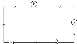
Follow the loop from the positive terminal of the cell, through the bulb, ammeter and plug key, back to the negative terminal — that is the conventional direction of current. The ammeter sits in series because the whole current must pass through it, and the bulb glows only when the key closes the circuit (p. 172).
Figure 11.2: The Ohm’s Law Experiment
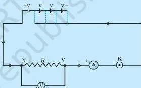
A nichrome wire XY is the test conductor. One to four cells change the potential difference, the ammeter reads current in series, and the voltmeter reads voltage across the wire in parallel. Plotting V against I for 1, 2, 3 and 4 cells gives a straight line through the origin — that linearity is Ohm’s law (p. 175).
Figure 11.5: What Changes Resistance
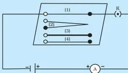
Wire (1) is the reference of length \( l \). Wire (2) doubles the length, wire (3) is thicker, and wire (4) is copper instead of nichrome. The ammeter shows the current halving when length doubles, rising when the wire thickens, and changing again for a different material — so resistance depends on length, area and material (p. 178).
Figures 11.6 and 11.7: Series and Parallel at a Glance
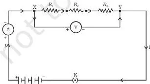
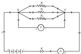
Series resistors sit end to end in one path, so the same current flows through all of them and the voltage splits. Parallel resistors hang between the same two points X and Y, so each branch sees the same voltage while the current splits. These two pictures are the reason for the two different equivalent-resistance formulas (p. 181-182).
Figure 11.9: A Series Circuit You Can Calculate
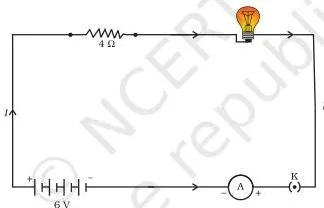
The \( 20\ \Omega \) lamp and the \( 4\ \Omega \) conductor carry the same current. The battery’s 6 V splits in proportion to resistance — 5 V across the lamp and 1 V across the conductor — and the total 24 \( \Omega \) gives 0.25 A. This figure is the visual meaning of series: voltage divides, current does not (p. 184).
Figure 11.13: Where the Heat Comes From
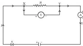
In a purely resistive circuit, every joule the source supplies is dissipated as heat in the resistor. Work done on a charge \( Q \) is \( VQ \), giving \( H = VIt \); with Ohm’s law this becomes \( H = I^2Rt \). The figure is the visual meaning of “energy in equals heat out” (p. 188-189).
Electricity Class 10 Glossary: Every Term Defined
The chapter builds one connected set of ideas — charge, current, voltage, resistance, resistivity, heat, power, energy. This table collects every term with a plain definition, its unit, and the NCERT page where it appears.
| Term | Plain definition | Unit | NCERT page |
|---|---|---|---|
| Electric current | Rate of flow of charge across a cross-section, \( I = Q/t \) | ampere (A) | p. 172 |
| Electric circuit | A continuous and closed path through which current flows | — | p. 171 |
| Potential difference | Work done per unit charge to move charge between two points, \( V = W/Q \) | volt (V) | p. 173 |
| Resistance | Property of a conductor that opposes the flow of charge; \( R = V/I \) at steady temperature | ohm (\( \Omega \)) | p. 176 |
| Resistivity | The material’s own resistance property, \( \rho = RA/l \), independent of the wire’s size | ohm metre (\( \Omega\,\text{m} \)) | p. 178 |
| Rheostat | Variable resistance used to regulate current without changing the voltage source | ohm (\( \Omega \)) | p. 176 |
| Joule’s law of heating | Heat produced in a resistor, \( H = I^2Rt \) | joule (J) | p. 189 |
| Electric power | Rate at which electric energy is consumed, \( P = VI \) | watt (W) | p. 191 |
| Kilowatt hour | Commercial unit of energy, \( 1\ \text{kWh} = 3.6 \times 10^6\ \text{J} \) | kWh | p. 191 |
| Fuse | Safety wire placed in series that melts and breaks the circuit when current exceeds its rating | rated in amperes | p. 190 |
Common Mistakes in Electricity Class 10 and How to Avoid Them
Most lost marks in this chapter come from a handful of repeatable slips rather than from hard problems. Check each one before you start a numerical.
| Mistake | Correct rule | How to check your answer |
|---|---|---|
| Drawing current in the direction electrons move | Conventional current is opposite to the flow of electrons | The current arrow runs from the positive terminal to the negative terminal outside the cell (p. 172) |
| Forgetting the temperature condition in Ohm’s law | \( V \propto I \) holds only while the wire’s temperature stays the same | State “at constant temperature” whenever you write the law (p. 176) |
| Leaving time in minutes instead of seconds | Convert to seconds before using \( Q = It \) or \( H = I^2Rt \) | 10 minutes → 600 s, as in Example 11.1 (p. 172) |
| Treating voltage as the same across series resistors | In series, current is common and voltage divides | Add the voltage drops; they must equal the supply voltage (p. 183-184) |
| Treating current as the same through parallel branches | In parallel, voltage is common and current divides | Add the branch currents; they must equal the total current (p. 186) |
| Assuming the parallel equivalent resistance is an average | It is smaller than the smallest branch resistance | Check that \( R_p \) is less than every branch resistance (p. 186) |
| Using a bulb’s rated power at a different voltage | The filament’s resistance is fixed; recompute \( P = V^2/R \) with the actual voltage | Find \( R \) from the rating first (\( R = V^2/P \)), then apply the new voltage |
| Believing electrons are consumed in a circuit | We pay for the energy delivered, not for electrons | Keep the book’s “More to Know” note in mind (p. 191) |
What the Six Activities in the Chapter Demonstrate
The six activities are not separate from the theory — each one is the experiment that produces a rule you then apply in numericals.
| Activity | NCERT page | What it demonstrates |
|---|---|---|
| 11.1 | p. 175 | For a given nichrome wire, \( V/I \) stays roughly constant; the V-I graph is a straight line through the origin — this becomes Ohm’s law |
| 11.2 | p. 176 | Different components draw different currents at the same voltage, so they have different resistances — good conductors, resistors and insulators |
| 11.3 | p. 177 | Resistance depends on length, area of cross-section and the material of the wire |
| 11.4 | p. 182 | The current is the same at every point of a series circuit, wherever the ammeter is placed |
| 11.5 | p. 183 | The total voltage across series resistors equals the sum of the individual voltages |
| 11.6 | p. 185 | The total current in a parallel circuit equals the sum of the branch currents, and every branch sees the same voltage |
Use this map while solving: activities 11.1 to 11.3 establish Ohm’s law and the factors of resistance; activities 11.4 to 11.6 establish the two combination rules.
How to Revise Electricity Class 10 for Exams
This chapter is numerical-heavy, so revision means working problems, not only re-reading. Work in this order, then use the end-of-chapter exercises as your testing ground.
- Definitions and units: current, potential difference, resistance, resistivity, power — and their SI units.
- Ohm’s law and its V-I graph: why the straight line through the origin is the law.
- Series and parallel equivalent resistance, and the two voltage/current rules.
- Heating effect and power: Joule’s law, the three power forms, and the kilowatt hour.
The end-of-chapter exercises break up like this. Questions 1-4 are multiple choice: cut-wire resistance ratio, the expression that is not power, a 220 V 100 W bulb at 110 V, and heat in series versus parallel.
Questions 5-17 are numericals and short problems — voltmeter connection, wire length from resistivity, slope of the V-I graph, unknown resistance, series current, the number of parallel resistors, combining 6 ohm resistors, lamps in parallel, oven coils, power in one resistor, two lamps, TV versus toaster energy, and heater heat rate.
Question 18 is reasoning: tungsten, alloys, series in domestic circuits, area of cross-section, and transmission wires.
Use the in-text questions after each section as quick checks, and close with the chapter’s own summary, “What you have learnt” (p. 192), as the final checklist.
Textbook contents and the examinable syllabus are not always identical — check the current official CBSE syllabus for what is examinable. The chapter that follows, Magnetic Effects of Electric Current, continues directly from these ideas.
For a faster pass the night before, the Class 10 Science notes and the Class 10 notes hub condense each chapter, and the Magnetic Effects of Electric Current notes cover the next chapter.
The Human Eye and the Colourful World notes sit in the same notes section for the optics topics earlier in the book; the main notes section has everything in one place.
Electricity Class 10: End-of-Chapter Recap
The chapter closes with its own summary — “What you have learnt” (p. 192) — and that list is the fastest way to check you know the chapter. Here it is rebuilt in fresh words as a bullet checklist and a formula table.
- Current is the rate of flow of charge; its SI unit is the ampere, and conventional current flows opposite to the electrons.
- A cell or battery maintains a potential difference, measured in volts, that drives the current.
- Resistance opposes the flow of charge. Ohm’s law, \( V \propto I \), holds at constant temperature.
- A wire’s resistance grows with its length, shrinks with area of cross-section, and depends on its material: \( R = \rho l/A \).
- Series equivalent resistance is the sum; parallel equivalent resistance follows the reciprocal rule.
- Electrical energy dissipated in a resistor is \( W = VIt \); heat from a steady current is \( H = I^2Rt \).
- Power is the rate of energy use, \( P = VI \), in watts; the commercial unit of energy is the kilowatt hour, \( 1\ \text{kWh} = 3.6 \times 10^6\ \text{J} \).
| Formula | What it gives | NCERT page |
|---|---|---|
| \( I = Q/t \) | current from charge and time | p. 172 |
| \( V = W/Q \) | potential difference from work and charge | p. 173 |
| \( V = IR \) | Ohm’s law (steady temperature) | p. 176 |
| \( R = \rho l/A \) | resistance of a uniform wire | p. 178 |
| \( R_s = R_1 + R_2 + R_3 \) | equivalent resistance in series | p. 184 |
| \( 1/R_p = 1/R_1 + 1/R_2 + 1/R_3 \) | equivalent resistance in parallel | p. 186 |
| \( H = VIt = I^2Rt \) | heat produced by a steady current | p. 188-189 |
| \( P = VI = I^2R = V^2/R \) | electric power | p. 191 |
| \( 1\ \text{kWh} = 3.6 \times 10^6\ \text{J} \) | commercial unit of energy | p. 191 |
Related Chapters and Resources
The rest of the Class 10 Science book is on this site chapter by chapter: the Science Class 10 book page lists them all. The previous chapter, Light – Reflection and Refraction, ends just before this one, and the next chapter, Magnetic Effects of Electric Current, follows it — both open from their own pages, alongside the Class 10 hub.
The complete Class 10 Science textbook is published on the NCERT website as chapter files; that textbook page lists every chapter of the book.
Reference: NCERT Class 10 Science textbook, chapter 11, official edition on ncert.nic.in.
Sources and Data Verification
- The sections, figures and contents described on this page come from the NCERT Class 10 Science textbook (Science, NCERT), Chapter 11 Electricity, in the edition currently published on ncert.nic.in.
- This page covers that single textbook chapter; it does not describe the full CBSE subject scheme.
- The listing is maintained for the 2026-27 academic session.
- NCERT settles textbook content, editions and PDFs; CBSE settles curriculum, syllabus and examinations.
Electricity Class 10: Frequently Asked Questions
What is the difference between resistance and resistivity in the Electricity chapter?
Resistance is a property of one particular conductor: it depends on the wire’s length, area and material, and its unit is the ohm (p. 176). Resistivity \( \rho \) is a property of the material itself, independent of the wire’s size, with unit ohm metre (p. 178). Two wires of the same metal can have different resistances but the same resistivity.
When should I use P = VI, P = I²R and P = V²/R?
All three are the same quantity (Eq. 11.22, p. 191), so choose the one that matches the data given: \( P = VI \) when you know voltage and current, \( P = I^2R \) when you know current and resistance, and \( P = V^2/R \) when you know voltage and resistance.
For a rated appliance at a changed voltage, first find the fixed resistance from its rating, then use \( P = V^2/R \).
Why are home appliances connected in parallel and not in series?
In parallel, every appliance gets the full mains voltage and draws its own current, and one appliance failing does not cut off the others. In series, all devices would have to take the same current, and one broken component would break the whole circuit (p. 187).
What does one unit on an electricity bill mean?
One unit means one kilowatt hour — the energy used by a 1 kW device in one hour, equal to \( 3.6 \times 10^6\ \text{J} \) (p. 191). The bill multiplies the units consumed by the price per unit.
Which chapter comes after Electricity in the NCERT Class 10 Science book?
Chapter 12, Magnetic Effects of Electric Current, follows Electricity. Its book page is linked in the related resources above.
Reference: NCERT Class 10 Science textbook, chapter 11, official edition on ncert.nic.in.
Explore Class 10 Science Books
Class 10 Science on LearnCBSE:
Related chapters:
- Chemical Reactions and Equations
- Acids, Bases and Salts
- Metals and Non-metals