Need the Wave Optics Class 12 formulas in one place? This sheet covers the formulas in the NCERT Class 12 Physics chapter Wave Optics: Huygens’ construction for reflection and refraction, Snell’s law and the critical angle, coherent interference and Young’s double-slit fringes, single-slit diffraction, and polarisation with Malus’ law.
Each formula is grouped by the textbook sub-topic it belongs to, with symbol meanings, units, when-to-use guidance and original worked examples. For the explanations and derivations behind these results, start from the Class 12 Physics formulas hub.
Formulas at a Glance
| Purpose (what you are finding) | Formula |
|---|---|
| Law of reflection from Huygens’ construction | \( i = r \) |
| Snell’s law of refraction | \( n_1 \sin i = n_2 \sin r \) |
| Speed of light in a medium | \( n = \frac{c}{v} \) |
| Wavelength change on refraction | \( \frac{\lambda_1}{\lambda_2} = \frac{v_1}{v_2} \) |
| Frequency unchanged on refraction | \( \frac{v_1}{\lambda_1} = \frac{v_2}{\lambda_2} \) |
| Critical angle | \( \sin i_c = \frac{n_2}{n_1} \) |
| Phase difference from path difference (from the interference examples) | \( \phi = \frac{2\pi}{\lambda} \Delta x \) |
| Resultant displacement for two identical coherent waves | \( y = 2a \cos\left(\frac{\phi}{2}\right) \cos\left(\omega t + \frac{\phi}{2}\right) \) |
| Resultant intensity for two coherent waves | \( I = 4I_0 \cos^2\left(\frac{\phi}{2}\right) \) |
| Constructive interference condition | \( S_1P \sim S_2P = n\lambda, \quad n = 0,1,2,\dots \) |
| Destructive interference condition | \( S_1P \sim S_2P = \left(n+\frac{1}{2}\right)\lambda, \quad n = 0,1,2,\dots \) |
| Incoherent sources, time-averaged intensity | \( I = 2I_0 \) |
| Young’s bright-fringe position | \( x_n = \frac{n\lambda D}{d}, \quad n = 0, \pm 1, \pm 2, \dots \) |
| Young’s dark-fringe position | \( x_n = \left(n+\frac{1}{2}\right)\frac{\lambda D}{d}, \quad n = 0, \pm 1, \pm 2, \dots \) |
| Single-slit diffraction minima | \( \theta_n \approx \frac{n\lambda}{a}, \quad n = \pm 1, \pm 2, \pm 3, \dots \) |
| Single-slit secondary maxima | \( \theta_n \approx \frac{\left(n+\frac{1}{2}\right)\lambda}{a} \) |
| Linearly polarised wave equations | \( y(x,t) = a\sin(kx-\omega t), \quad z(x,t) = a\sin(kx-\omega t) \) |
| Angular frequency and wavelength of a wave | \( \omega = 2\pi\nu, \quad \lambda = \frac{2\pi}{k} \) |
| Malus’ law | \( I = I_0 \cos^2 \theta \) |
| Intensity through a sheet between crossed polaroids (from Example 10.2) | \( I = \frac{I_0}{4}\sin^2 2\theta \) |
All Formulas, Grouped by Topic
Huygens Principle: Refraction and Reflection of a Plane Wave
A wavefront is a surface of constant phase. Huygens’ principle says every point on a wavefront acts as a source of secondary wavelets, and the new wavefront is the forward envelope of these wavelets (NCERT, p. 3).
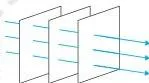
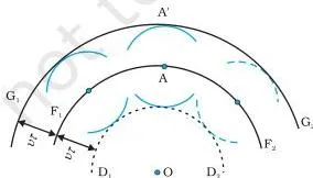
The first diagram shows a diverging spherical wave. The second shows why a small portion of a spherical wave far from the source can be treated as a plane wave.
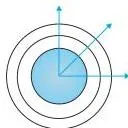
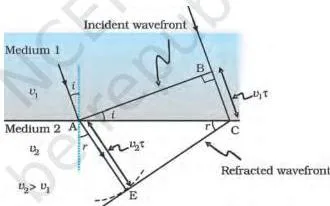
The construction produces spherical secondary wavelets of radius \( v\tau \). Using this geometry for a plane wave crossing an interface gives the refraction formulas (NCERT, p. 4):
\[ \frac{\sin i}{\sin r} = \frac{v_1}{v_2} \quad \text{(10.3)} \]\[ n_1 = \frac{c}{v_1}, \qquad n_2 = \frac{c}{v_2} \quad \text{(10.4, 10.5)} \]\[ n_1 \sin i = n_2 \sin r \quad \text{(10.6)} \]
In these formulas, \( i \) and \( r \) are measured from the normal. If a wave enters a denser medium, its speed and wavelength decrease but its frequency stays the same (NCERT, p. 5):
\[ \frac{\lambda_1}{\lambda_2} = \frac{v_1}{v_2} \quad \text{and} \quad \frac{v_1}{\lambda_1} = \frac{v_2}{\lambda_2} \quad \text{(10.7)} \]
Applying Huygens’ construction to a plane reflecting surface gives the law of reflection: the incident and reflected angles are equal (NCERT, p. 6).
\[ i = r \]
When light goes from a denser to a rarer medium, the wave bends away from the normal. The critical angle is the angle of incidence for which the refracted angle would be \( 90^\circ \):
\[ \sin i_c = \frac{n_2}{n_1} \quad \text{(10.8)} \]
For an incidence angle greater than \( i_c \), there is no refracted wave and the light undergoes total internal reflection (NCERT, p. 6).
Interference: Coherent and Incoherent Addition of Waves
Interference follows from the superposition principle: at any point, the resultant displacement is the vector sum of the displacements of the individual waves. Two sources are coherent when the phase difference between their waves at a point does not change with time (NCERT, p. 8).
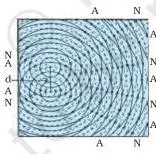
For two waves of the same amplitude \( a \) and phase difference \( \phi \), the resultant displacement is
\[ y = 2a\cos\left(\frac{\phi}{2}\right)\cos\left(\omega t + \frac{\phi}{2}\right) \]
and the resultant intensity is
\[ I = 4I_0 \cos^2\left(\frac{\phi}{2}\right) \quad \text{(10.11)} \]
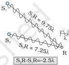
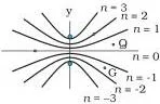
The phase difference is linked to the path difference by \( \phi = \frac{2\pi}{\lambda}\Delta x \). For two coherent sources vibrating in phase, constructive interference occurs when the path difference is a whole number of wavelengths, and destructive interference when it is a half-integer number of wavelengths (NCERT, p. 10):
\[ S_1P \sim S_2P = n\lambda, \quad n = 0,1,2,\dots \quad \text{(10.9)} \]\[ S_1P \sim S_2P = \left(n+\frac{1}{2}\right)\lambda, \quad n = 0,1,2,\dots \quad \text{(10.10)} \]
The diagrams below show these two cases.
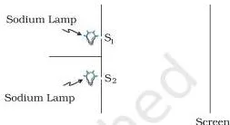
If the sources are incoherent, the phase difference changes rapidly and the time-averaged intensity becomes uniform:
\[ I = 2I_0 \quad \text{(10.12)} \]
Young’s Double-Slit Experiment
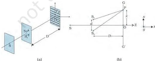
Young made two pinholes \( S_1 \) and \( S_2 \) very close together and illuminated them from one source, so the two pinholes behaved as coherent sources (NCERT, p. 11). For slit separation \( d \) and screen distance \( D \), bright fringes satisfy \( xd/D = n\lambda \) and dark fringes satisfy \( xd/D = (n+1/2)\lambda \). Therefore:
\[ x_n = \frac{n\lambda D}{d}, \quad n = 0, \pm 1, \pm 2, \dots \quad \text{(10.13)} \]\[ x_n = \left(n+\frac{1}{2}\right)\frac{\lambda D}{d}, \quad n = 0, \pm 1, \pm 2, \dots \quad \text{(10.14)} \]
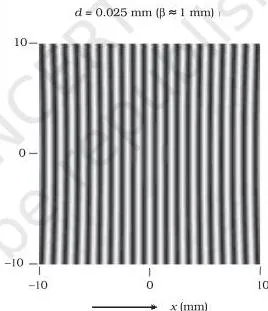
These equations show that the bright and dark fringes are equally spaced (NCERT, p. 12).
Diffraction by a Single Slit
Diffraction is a general property of waves. When a parallel beam of monochromatic light falls normally on a single slit of width \( a \), the intensity has a central maximum at \( \theta = 0 \), with weaker secondary maxima on either side. The minima occur at (NCERT, p. 13):
\[ \theta_n \approx \frac{n\lambda}{a}, \quad n = \pm 1, \pm 2, \pm 3, \dots \]
and the weaker secondary maxima lie near
\[ \theta_n \approx \frac{\left(n+\frac{1}{2}\right)\lambda}{a} \]
The geometry below shows how different parts of the slit act as secondary sources, with path differences that produce the minima.
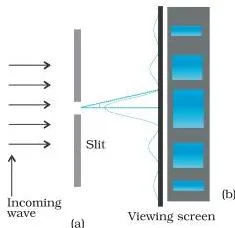
The double-slit pattern is actually a superposition of single-slit diffraction from each slit and the double-slit interference pattern. In interference and diffraction, light energy is redistributed, not lost (NCERT, p. 14).
Polarisation
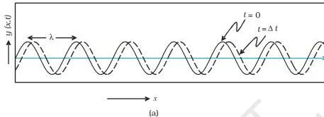
Light waves are transverse: the electric field is perpendicular to the direction of propagation. A wave polarised along the y-direction and one polarised along the z-direction are written as (NCERT, p. 15):
\[ y(x,t) = a\sin(kx – \omega t) \quad \text{(10.15)} \]\[ z(x,t) = a\sin(kx – \omega t) \quad \text{(10.17)} \]
with angular frequency and wavelength given by
\[ \omega = 2\pi\nu, \qquad \lambda = \frac{2\pi}{k} \quad \text{(10.16)} \]
A polaroid transmits only the component of the electric field along its pass-axis. For polarised light of intensity \( I_0 \) entering a second polaroid, the transmitted intensity follows Malus’ law (NCERT, p. 16):
\[ I = I_0 \cos^2 \theta \quad \text{(10.18)} \]
Here \( \theta \) is the angle between the pass-axes of the two polaroids. Unpolarised light through a single polaroid is reduced to half its incident intensity (NCERT, p. 16).
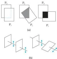
When a polaroid sheet is rotated between two crossed polaroids, the emerging intensity is (Example 10.2):
\[ I = I_0 \cos^2 \theta \sin^2 \theta = \frac{I_0}{4}\sin^2 2\theta \]
This is maximum when the middle sheet makes an angle \( \theta = \pi/4 \) with the first polaroid.
If you need formulas from earlier chapters, browse the full Physics formulas collection.
What Each Symbol Means
| Symbol | What it means | SI unit |
|---|---|---|
| \( i \) | Angle of incidence | radian (dimensionless) |
| \( r \) | Angle of refraction | radian (dimensionless) |
| \( i_c \) | Critical angle | radian (dimensionless) |
| \( n, n_1, n_2 \) | Refractive index of a medium (or of medium 1, medium 2) | dimensionless |
| \( c \) | Speed of light in vacuum | m/s |
| \( v, v_1, v_2 \) | Speed of light in a medium | m/s |
| \( \lambda, \lambda_1, \lambda_2 \) | Wavelength in a medium (or in medium 1, medium 2) | m |
| \( \nu \) | Frequency of light | Hz |
| \( k \) | Angular wave number | rad/m |
| \( \omega \) | Angular frequency | rad/s |
| \( t \) | Time | s |
| \( y, z \) | Displacement of the wave along the y- or z-direction | m |
| \( a \) | Amplitude of a wave; also used for slit width in diffraction | m |
| \( \phi \) | Phase difference between two waves | radian (dimensionless) |
| \( \Delta x \) | Path difference between two waves | m |
| \( S_1P \sim S_2P \) | Difference between the distances from two sources \( S_1, S_2 \) to a point P | m |
| \( I_0 \) | Intensity of one source, or intensity of polarised light entering a polaroid | \( \text{W/m}^2 \) |
| \( I \) | Resultant or transmitted intensity | \( \text{W/m}^2 \) |
| \( d \) | Separation between the two slits in Young’s experiment | m |
| \( D \) | Distance from the slits to the screen | m |
| \( x_n \) | Position of the nth bright or dark fringe from the central maximum | m |
| \( n \) | Integer order in interference and diffraction conditions | dimensionless (count) |
| \( \theta \) | Diffraction angle, or angle between polaroid pass-axes | radian (dimensionless) |
Note: the symbol \( n \) is used in two ways in this chapter — refractive index in \( n = c/v \), and integer order in \( x_n = n\lambda D/d \). Check the context before substituting.
When to Use Each Formula
| Formula | Use it when | Condition to check |
|---|---|---|
| \( i = r \) | Finding the reflected angle from a plane surface | Angles are measured from the normal |
| \( n_1 \sin i = n_2 \sin r \) | Finding the refracted angle at a plane interface | Angles measured from the normal; media on both sides of the surface |
| \( n = c/v \) | Converting between refractive index and speed of light in a medium | \( v \) is the speed in that medium |
| \( \lambda_1/\lambda_2 = v_1/v_2 \) | Finding how wavelength changes when light enters another medium | Frequency stays unchanged |
| \( \sin i_c = n_2/n_1 \) | Light travels from a denser to a rarer medium; finding where total internal reflection starts | \( n_2 \lt n_1 \); for \( i \gt i_c \) there is no refracted wave |
| \( I = 4I_0\cos^2(\phi/2) \) | Finding intensity at a point from two coherent sources with known phase difference | Sources have the same frequency and a steady phase difference |
| Path difference conditions \( n\lambda \) and \( (n+\frac12)\lambda \) | Deciding whether a point is a bright or dark fringe | Coherent sources vibrating in phase |
| \( I = 2I_0 \) | Two independent or incoherent sources illuminate the same screen | Phase difference changes rapidly; no stable fringes form |
| \( x_n = n\lambda D/d \) and \( (n+\frac12)\lambda D/d \) | Locating bright and dark fringes in Young’s double-slit experiment | \( d \) is slit separation, \( D \) is slit-to-screen distance |
| \( \theta \approx n\lambda/a \) | Finding diffraction minima of a single slit | Small-angle approximation; \( a \) is slit width and \( \theta \) is in radians |
| \( I = I_0\cos^2\theta \) | Finding intensity after polarised light passes through a polaroid | \( \theta \) is the angle between pass-axes |
| \( I = (I_0/4)\sin^2 2\theta \) | Polaroid sheet rotated between two crossed polaroids | The first and last polaroids are crossed; maximum at \( \theta = \pi/4 \) |
Worked Examples
Worked Example 1: Finding the wavelength of light in Young’s double-slit experiment
Step 1: Use the bright-fringe formula \( x_n = \frac{n\lambda D}{d} \) because the position of the \( n=3 \) bright fringe is given.
Step 2: Rearrange to \( \lambda = \frac{x_n d}{nD} \).
Substitute \( x_3 = 5.0\times10^{-3}\ \text{m} \), \( d = 4.5\times10^{-4}\ \text{m} \), \( D = 1.5\ \text{m} \):
\[ \lambda = \frac{(5.0\times10^{-3})(4.5\times10^{-4})}{3\times1.5} = 5.0\times10^{-7}\ \text{m} \]
Final answer: \( \lambda = 500\ \text{nm} \).
Worked Example 2: First minimum of a single-slit diffraction pattern
Step 1: Use the single-slit minimum condition \( \theta \approx \frac{\lambda}{a} \) for the first minimum, \( n=1 \).
Step 2: Substitute \( \lambda = 6.25\times10^{-7}\ \text{m} \) and slit width \( a = 2.5\times10^{-4}\ \text{m} \):
\[ \theta \approx \frac{6.25\times10^{-7}}{2.5\times10^{-4}} = 2.5\times10^{-3}\ \text{rad} \]
\[ \theta \approx 2.5\times10^{-3} \times \frac{180}{\pi} \approx 0.14^\circ \]
Final answer: The first minimum lies at about \( 2.5\times10^{-3}\ \text{rad} \), or roughly \( 0.14^\circ \), from the central maximum.
Worked Example 3: A polaroid sheet rotated between two crossed polaroids
Step 1: For a sheet between crossed polaroids, the emerging intensity is \( I = \frac{I_0}{4}\sin^2 2\theta \), where \( I_0 \) is the intensity after the first polaroid and \( \theta \) is the angle the middle sheet makes with the first pass-axis.
Step 2: Substitute \( I_0 = 16\ \text{W/m}^2 \) and \( \theta = 30^\circ \):
\[ I = \frac{16}{4}\sin^2 60^\circ = 4\left(\frac{\sqrt{3}}{2}\right)^2 = 3\ \text{W/m}^2 \]
Final answer: The transmitted intensity is \( 3\ \text{W/m}^2 \). The maximum possible transmitted intensity occurs when \( \theta = 45^\circ \).
Common Mistakes to Avoid
| Mistake | Correct rule | How to check your answer |
|---|---|---|
| Writing bright fringes at \( (n+\frac12)\lambda \) and dark fringes at \( n\lambda \) | Bright: path difference \( = n\lambda \). Dark: path difference \( = (n+\frac12)\lambda \). | Put \( n=0 \): the central fringe must be bright at \( x=0 \). If your formula puts a dark fringe at \( x=0 \), the conditions are swapped. |
| Using \( \theta \approx n\lambda/a \) without checking that \( \theta \) is small | This is the small-angle approximation, and \( \theta \) must be in radians. | Convert your final angle to degrees; if it is not small, the approximation may not hold. |
| Applying Malus’ law directly to unpolarised light | Malus’ law applies to polarised light entering a polaroid. Unpolarised light through one polaroid is reduced to half. | Rotate the first polaroid: if the transmitted intensity does not change, the beam is unpolarised and Malus’ law is not the first step. |
| Swapping \( d \) and \( D \) in Young’s experiment | \( d \) is the slit separation and \( D \) is the slit-to-screen distance. | Check units: \( x_n = n\lambda D/d \). Increasing \( D \) or decreasing \( d \) should spread the fringes farther apart. |
| Confusing the two uses of the symbol \( a \) | In \( I = 4I_0\cos^2(\phi/2) \), \( a \) is the wave amplitude. In \( \theta \approx n\lambda/a \), \( a \) is the slit width. | In the diffraction formula, \( a \) is divided into \( \lambda \), so \( a \) must be the slit width with units of length. |
Frequently Asked Questions
Are the fringes in Young’s double-slit experiment equally spaced?
Yes. Subtracting successive positions from Eq. (10.13) gives a constant spacing \( \lambda D/d \), so the bright fringes, and similarly the dark fringes, are equally spaced (NCERT, p. 12).
Why do two sodium lamps not produce interference fringes?
Two independent lamps have no fixed phase relationship; the phase changes abruptly in about \( 10^{-10} \) seconds. The pattern therefore averages to a uniform intensity \( I = 2I_0 \), and no stable fringes are seen (NCERT, p. 11).
What is the difference between interference and diffraction?
There is no sharp physical difference between the two. Roughly, interference is the term used when a few sources are superposed, while diffraction describes the effect of many secondary sources. The double-slit pattern is itself a superposition of single-slit diffraction and double-slit interference (NCERT, p. 14).
In Malus’ law, what exactly are \( \theta \) and \( I_0 \)?
\( \theta \) is the angle between the pass-axes of the two polaroids, and \( I_0 \) is the intensity of the polarised light entering the second polaroid. For unpolarised incident light, the first polaroid already reduces the intensity by half.
Reference: NCERT Class 12 Physics textbook, chapter Wave Optics. Verify any formula against the official NCERT website.
Explore Class 12 Physics Formulas
More for this chapter:
Class 12 Physics on LearnCBSE:
Related chapters:
Official source: download the NCERT textbook free from ncert.nic.in.