
These wave optics class 12 notes compress the whole NCERT Chapter 10 (Wave Optics, Physics Part II) into one revision-ready page: wavefronts and the Huygens construction, the wave-theory derivation of Snell’s law, interference and Young’s experiment, single-slit diffraction, polarisation and Malus’ law — with formulas, worked examples and exam-level pointers.
Each section ends where the next begins, so you can revise in order or jump straight to the section you need. The formula sheet and common-mistakes table are designed for the night before the test.
Every claim here traces to the official textbook — verify any derivation directly in the NCERT Class 12 Physics Part II PDF. For the rest of the course, browse the Class 12 Physics notes hub.
Why Wave Optics: Light as a Wave, Not a Ray
Class 12 Physics treats light in two ways. Geometrical (ray) optics assumes light travels in straight lines; wave optics treats light as a wave and explains reflection, refraction, interference, diffraction and polarisation from one principle (NCERT, p. 256).
The historical clash between two models settled which picture is correct:
| Model | Who | Prediction for a denser medium | Outcome |
|---|---|---|---|
| Corpuscular | Descartes (1637), Newton’s OPTICKS | Light travels faster | Wrong |
| Wave | Huygens (1678) | Light travels slower | Correct — Foucault’s experiment (1850) |
- Young (1801): interference experiment — firmly established light as a wave.
- Maxwell: light is an electromagnetic wave — solving the problem of how a wave crosses vacuum.
Why do rays still work for everyday optics? Visible wavelengths are tiny — yellow light is about 0.6 µm (NCERT, p. 256) — far smaller than typical lenses and mirrors. Geometrical optics is the limit in which wavelength tends to zero. This chapter builds four phenomena on one idea — superposition: interference, diffraction, then polarisation.
Ray optics itself is revised in the ray optics and optical instruments notes.
Huygens Principle: Wavefronts and Secondary Wavelets
A wavefront is a surface of constant phase — the locus of all points oscillating in phase (NCERT, p. 257). Drop a stone in still water: circular rings of maximum disturbance spread out, and every point on one ring is at the same distance from the source, so all points on it oscillate together.
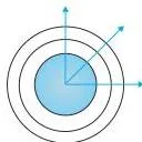
- A point source radiating uniformly gives spherical wavefronts (Fig. 10.1a).
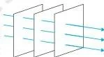
- Far from the source, a small patch of a sphere looks flat — the plane wave approximation (Fig. 10.1b).
- Energy travels perpendicular to the wavefront; that perpendicular direction is the ray.
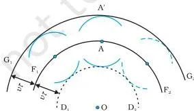
Huygens principle (NCERT, p. 257–258): every point on a wavefront acts as a source of secondary wavelets that spread out in all directions with the wave speed v. To find the wavefront after time τ, draw spheres of radius vτ from every point; the common tangent — the envelope — is the new wavefront.
One shortcoming: the construction also predicts a backwave (D1D2 in Fig. 10.2). Huygens fixed it with an ad hoc assumption — secondary wavelet amplitude is maximum in the forward direction and zero backward (NCERT, p. 258).
Analogy: imagine a marching line of people. Each person steps forward the same distance in the same time; the line’s new shape is the envelope of everyone’s step. Nobody steps backward — that is why the backwave vanishes. The line itself is the wavefront; the direction each person faces is the ray.
Refraction and Reflection from Huygens Construction
This derivation is the most likely one to appear in the exam. Take a plane wavefront AB incident on the interface PP′ at angle i. In time τ, the point B travels to C, so BC = v1τ.
Meanwhile a secondary wavelet from A spreads into medium 2 with radius v2τ; the tangent from C to that wavelet is the refracted wavefront CE (NCERT, p. 258).
\[ \sin i = \frac{BC}{AC} = \frac{v_1 \tau}{AC}, \qquad \sin r = \frac{AE}{AC} = \frac{v_2 \tau}{AC} \]
Dividing the two gives the central result:
\[ \frac{\sin i}{\sin r} = \frac{v_1}{v_2} \tag{10.3} \]
With refractive indices defined as \( n_1 = c/v_1 \) and \( n_2 = c/v_2 \), this becomes Snell’s law (NCERT, p. 259):
\[ n_1 \sin i = n_2 \sin r \tag{10.6} \]
Why the wave model won: if the ray bends toward the normal (r < i), Eq. (10.3) says \( v_2 \lt v_1 \) — light is slower in the denser medium. The corpuscular model predicted the opposite; Foucault’s 1850 experiment confirmed the wave prediction.
Wavelength changes, frequency does not. If BC equals one wavelength λ1 in medium 1, then AE equals λ2 in medium 2 in the same time τ (NCERT, p. 259):
\[ \frac{\lambda_1}{\lambda_2} = \frac{v_1}{v_2} \quad \Rightarrow \quad \frac{v_1}{\lambda_1} = \frac{v_2}{\lambda_2} \tag{10.7} \]
So in a denser medium, speed and wavelength both decrease but frequency ν = v/λ stays constant. This is the chapter’s key conceptual trap — see the misconception autopsy below.
Refraction at a rarer medium and total internal reflection
When \( v_2 \gt v_1 \), the wave bends away from the normal (NCERT, p. 260). The critical angle is defined by \[ \sin i_c = \frac{n_2}{n_1} \tag{10.8} \]
At \( i = i_c \), \( \sin r = 1 \) so \( r = 90^\circ \). For \( i \gt i_c \) no refracted wave exists — that is total internal reflection.
Law of reflection
For reflection from a plane surface MN, the construction uses one medium: AE = BC = vτ. Triangles EAC and BAC are congruent, so the angles of incidence and reflection are equal — the law of reflection (NCERT, p. 260–261).
Wavefronts also explain optical instruments (NCERT, p. 261): a prism tilts the emerging wavefront, a convex lens delays the central part most and makes the wavefront spherical — converging at the focus F — and a concave mirror does the same on reflection. The equal-time principle follows: the total time from an object point to its image is the same along any ray.
Misconception autopsy — “frequency changes on refraction.” Students often think that because speed drops, frequency must drop too. Correct: frequency never changes when light refracts. Reflection and refraction happen through interaction with the atomic constituents of the medium; atoms act as oscillators forced at the incident frequency, so they re-emit at that same frequency (NCERT, p. 262, Example 10.1a).
Energy also does not fall with speed — a wave’s energy depends on its amplitude, not its speed (Example 10.1b).
Interference: Coherent and Incoherent Addition of Waves
The superposition principle: at any point, the resultant displacement from several waves is the vector sum of the individual displacements (NCERT, p. 262). This single rule produces interference, diffraction and (later) polarisation behaviour.
Two sources are coherent when their phase difference at any point does not change with time — like two needles S1 and S2 oscillating up and down in phase in water (NCERT, p. 262).
- Where \( S_1P = S_2P \), the waves arrive in phase: \( y = 2a \cos \omega t \), so I = 4I0 — constructive interference.
- Path difference nλ → still in phase → I = 4I0 (constructive, bright).
- Path difference (n + 1/2)λ → completely out of phase → displacements cancel → I = 0 (destructive, dark).
\[ S_1P \sim S_2P = n\lambda \quad (n = 0, 1, 2, \dots) \quad \text{bright} \tag{10.9} \]
\[ S_1P \sim S_2P = \left(n + \frac{1}{2}\right)\lambda \quad \text{dark} \tag{10.10} \]
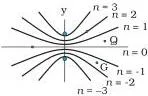
The figure shows why: at R the path difference is 2.5λ, so a crest from one source meets a trough from the other and the displacement cancels to zero.
General case. For an arbitrary phase difference φ between the two waves, the resultant intensity is (NCERT, p. 264):
\[ I = 4I_0 \cos^2 \left( \frac{\phi}{2} \right) \tag{10.11} \]
When φ = 0, ±2π, ±4π, … you recover Eq. (10.9); when φ = ±π, ±3π, … you recover Eq. (10.10).
Incoherent sources have a phase difference that changes rapidly with time — the averaged intensity is just the sum:
\[ I = 2I_0 \quad \text{at every point} \tag{10.12} \]
Memory device: “Whole numbers of λ are bright — no halves allowed; the half-integers are dark.” If the path difference contains a whole number of wavelengths, the waves lock in step; a half-integer forces them out of step.
Young’s Double Slit Experiment: Why Two Lamps Fail
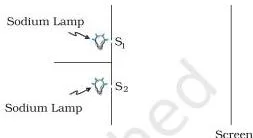
The puzzle: two sodium lamps illuminating two pinholes produce no fringes. The reason: an ordinary source like a sodium lamp undergoes abrupt phase changes in about 10⁻¹⁰ seconds, so two independent sources have no fixed phase relationship — they are incoherent and their intensities simply add (NCERT, p. 265).
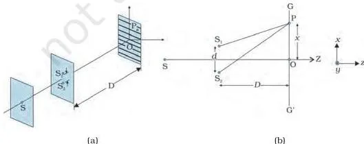
Young’s trick — locking the phases: one pinhole S, lit by a bright source, feeds two close pinholes S1 and S2. Any abrupt phase change in S appears identically in the light reaching S1 and S2, so the two sources stay coherent (NCERT, p. 265). The spherical waves from S1 and S2 then produce stable fringes on the screen GG′.
Fringe positions. With slit separation d and screen distance D (NCERT, p. 265):
\[ x_n = \frac{n\lambda D}{d} \quad \text{(bright fringes)} \tag{10.13} \]
\[ x_n = \left(n + \frac{1}{2}\right)\frac{\lambda D}{d} \quad \text{(dark fringes)} \tag{10.14} \]
The fringe width — the distance between consecutive bright fringes — is therefore \[ \beta = \frac{\lambda D}{d} \]
Bright and dark fringes are equally spaced. To see fringes clearly you need a small d and a large D — that is why the experiment uses two pinholes very close together on a distant screen.
Diffraction at a Single Slit
Diffraction is the spreading of waves around corners — the reason you hear someone talking around a wall but need a clear line of sight to see them (NCERT, p. 266–267). Light diffracts too, but because its wavelength is tiny, the effect is only noticeable through narrow slits.
For a single slit of width a, treat every part of the slit as a secondary source in phase (Fig. 10.14). Rays to a distant point P make an angle θ with the normal; the contributions from different parts of the slit arrive with different phases and add up with cancellation at certain angles (NCERT, p. 267).
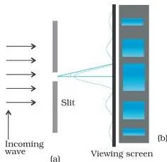
Resulting pattern (NCERT, p. 267):
- Central maximum at θ = 0 — the brightest and widest feature.
- Minima (zero intensity) at \( \theta \approx n\lambda/a \), n = ±1, ±2, ±3, …
- Secondary maxima at \( \theta \approx (n + 1/2)\lambda/a \) — each weaker than the last.
The central maximum is twice as wide as the others: the first minima on either side sit at \( \pm\lambda/a \), so the central region spans an angular width \( 2\lambda/a \), while each secondary maximum spans only \( \lambda/a \) between neighbouring minima.
Interference vs diffraction — the comparison every student needs:
| Feature | Interference (double slit) | Diffraction (single slit) |
|---|---|---|
| Sources | Two coherent sources (S1, S2) | Many secondary sources — every part of one slit |
| Superposition of | Two separate waves | Wavelets from one wavefront |
| Fringe width | All fringes equally spaced, β = λD/d | Central maximum twice as wide as the rest |
| Intensity | Bright fringes of comparable intensity | Secondary maxima become weaker with n |
| Minima | Near-zero at (n + 1/2)λ path difference | Exact zeros at θ ≈ nλ/a |
Feynman’s verdict (NCERT, p. 267–268): “No one has ever been able to define the difference between interference and diffraction satisfactorily… when there are only a few sources… the result is usually called interference, but if there is a large number of them… the word diffraction is more often used.”
In fact, the double-slit pattern is single-slit diffraction from each slit superposed on two-slit interference.
Two practical points: light energy is redistributed in interference and diffraction — dark regions lose energy that appears in bright regions, consistent with conservation (NCERT, p. 268). And you can see single-slit diffraction at home: hold two razor blades edge-to-edge to form a narrow slit and view a straight-filament bulb through it (NCERT, p. 268).
Polarisation and Malus’ Law
Hold a long horizontal string and shake one end up and down: a transverse wave travels along +x, described by \( y(x,t) = a \sin(kx – \omega t) \) (NCERT, p. 269). The string stays confined to the x–y plane — that is a linearly (plane) polarised wave.
If you randomly change the direction of shaking, the plane of vibration changes randomly — an unpolarised wave.
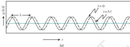
Light waves are transverse: the electric field is always perpendicular to the direction of propagation. A polaroid contains long chain molecules aligned along one direction; they absorb the electric vector along that direction. The pass-axis is perpendicular to the aligned molecules — the direction along which the electric vector survives (NCERT, p. 270).
- Unpolarised light through one polaroid → intensity halved: I = I₀/2.
- Polarised light through a second polaroid whose pass-axis makes angle θ → Malus’ law:
\[ I = I_0 \cos^2 \theta \tag{10.18} \]
Here I₀ is the intensity after the first polaroid, and θ is the angle between the two pass-axes. Turning the second polaroid from 0° to 90° smoothly drops the transmitted intensity from full to zero (NCERT, p. 270–271).
Crossed polaroids (90°) transmit nothing. But Example 10.2 shows a beautiful result: insert a third polaroid between two crossed ones, rotated by θ. The emerging intensity is (NCERT, p. 271):
\[ I = I_0 \cos^2 \theta \sin^2 \theta = \frac{I_0}{4} \sin^2 2\theta \]
which is maximum at θ = 45°. Light that was fully blocked can be partially transmitted by adding a polaroid — a classic exam favourite.
Real-life application — polarised sunglasses. Glare from a lake or a wet road is reflected light, and reflection from a flat surface preferentially polarises light horizontally. Sunglass lenses with a vertical pass-axis absorb that horizontal component, so the bright glare is cut while the rest of the scene stays visible.
This is why polarised sunglasses, windowpanes and camera filters use polaroids (NCERT, p. 271 lists the uses; the glare mechanism goes one step further).
Wave Optics Class 12 Notes: Definitions Quick-Reference
All the terms you must be able to define in one line, with the chapter context where they appear.
| Term | Meaning | Example / context |
|---|---|---|
| Wavefront | Surface of constant phase — all points oscillate in phase | Circular rings on water from a dropped stone |
| Coherent sources | Sources with a constant phase difference that does not vary with time | Pinholes S1, S2 fed from one source in Young’s experiment |
| Incoherent sources | Phase difference changes rapidly with time | Two independent sodium lamps (phase flips ~10⁻¹⁰ s) |
| Constructive interference | Path difference nλ; waves arrive in phase → I = 4I₀ | Bright fringes in Young’s experiment |
| Destructive interference | Path difference (n + 1/2)λ; waves arrive out of phase → I = 0 | Dark fringes in Young’s experiment |
| Fringe width | Distance between consecutive bright (or dark) fringes, β = λD/d | Young’s double slit, equally spaced fringes |
| Diffraction | Spreading of waves around corners of an obstacle or slit | Single-slit pattern on a screen |
| Polarisation | Restriction of the electric vector to one direction of oscillation | Light transmitted through a polaroid |
| Unpolarised light | Electric vector changes direction rapidly and randomly, always perpendicular to propagation | Natural light from the Sun |
| Linearly (plane) polarised light | Electric vector oscillates along a single straight line | Output of a polaroid |
| Pass-axis | Direction along which the electric vector passes; perpendicular to the aligned molecules of a polaroid | Polaroid P₁ in the Malus’ law experiment |
| Critical angle | Angle of incidence for which r = 90°; sin ic = n₂/n₁ | Total internal reflection at a rarer medium |
| Superposition principle | Resultant displacement at a point is the vector sum of individual displacements | Basis of interference and diffraction |
Wave Optics Class 12 Notes: Formula Sheet with Symbols and Units
Every formula in the chapter on one table. Symbols: i, r = angles of incidence and refraction; v = speed (m s⁻¹); λ = wavelength (m); ν = frequency (Hz); n = refractive index (dimensionless); D = screen distance (m); d = slit separation (m); x = fringe position (m); a = slit width (m); θ = angle (rad); I = intensity (W m⁻²).
| Concept | Formula | Symbols (units) |
|---|---|---|
| Snell’s law (speeds) | \( \frac{\sin i}{\sin r} = \frac{v_1}{v_2} \) | v₁, v₂ (m s⁻¹) |
| Snell’s law (indices) | \( n_1 \sin i = n_2 \sin r \) | n₁, n₂ (dimensionless) |
| Wavelength and speed | \( \frac{\lambda_1}{\lambda_2} = \frac{v_1}{v_2} \) — ν constant | λ (m), v (m s⁻¹) |
| Critical angle | \( \sin i_c = \frac{n_2}{n_1} \) | i_c (degrees or rad) |
| Constructive interference | \( S_1P \sim S_2P = n\lambda \) → I = 4I₀ | λ (m), I (W m⁻²) |
| Destructive interference | \( S_1P \sim S_2P = (n + \frac{1}{2})\lambda \) → I = 0 | λ (m) |
| General resultant intensity | \( I = 4I_0 \cos^2(\phi/2) \) | φ (rad) |
| Incoherent sources | I = 2I₀ at every point | I (W m⁻²) |
| Bright fringe position | \( x = \frac{n\lambda D}{d} \) | D, d, x (m) |
| Dark fringe position | \( x = (n + \frac{1}{2})\frac{\lambda D}{d} \) | D, d, x (m) |
| Fringe width | \( \beta = \frac{\lambda D}{d} \) | β (m) |
| Single-slit minima | \( \theta \approx \frac{n\lambda}{a} \) | θ (rad), a (m) |
| Single-slit secondary maxima | \( \theta \approx (n + \frac{1}{2})\frac{\lambda}{a} \) | θ (rad), a (m) |
| Plane wave equation | \( y = a \sin(kx – \omega t) \) with \( \lambda = \frac{2\pi}{k} \) | k (m⁻¹), ω (rad s⁻¹) |
| Malus’ law | \( I = I_0 \cos^2 \theta \) | θ = angle between pass-axes |
Worked Examples: Three Solved Problems, Step by Step
Example 1: Fringe width in Young’s experiment
Method: use the fringe-width formula \( \beta = \lambda D/d \) — no derivation needed, just careful unit conversion.
Step 1: Write the data in SI units.
d = 0.40 mm = \( 0.40 \times 10^{-3}\,\text{m} \); D = 1.5 m; λ = 550 nm = \( 550 \times 10^{-9}\,\text{m} \).
Step 2: State the formula: \( \beta = \lambda D/d \).
\[ \beta = \frac{550 \times 10^{-9} \times 1.5}{0.40 \times 10^{-3}} \]
\[ \beta = \frac{825 \times 10^{-9}}{0.40 \times 10^{-3}} = 2062.5 \times 10^{-6}\,\text{m} = 2.06 \times 10^{-3}\,\text{m} \]
Final answer: β = 2.06 mm.
Example 2: Malus’ law through two polaroids
Method: unpolarised light is halved by the first polaroid; then apply Malus’ law with the angle between the pass-axes.
- Step 1: Unpolarised light of intensity I₀ through the first polaroid: \( I_1 = I_0/2 \).
- Step 2: The second polaroid has its pass-axis at 60° to the first.
Apply Malus’ law: \( I_2 = I_1 \cos^2 60^\circ \).
\[ I_2 = \frac{I_0}{2} \times \left(\frac{1}{2}\right)^2 = \frac{I_0}{2} \times \frac{1}{4} = \frac{I_0}{8} \]
Final answer: \( I_2 = I_0/8 \).
Example 3: First minimum of single-slit diffraction
Method: the first minimum satisfies \( \theta \approx \lambda/a \).
- Step 1: Convert to SI: a = 0.12 mm = \( 0.12 \times 10^{-3}\,\text{m} \); λ = 600 nm = \( 600 \times 10^{-9}\,\text{m} \).
- Step 2: Substitute into \( \theta \approx \lambda/a \):
\[ \theta \approx \frac{600 \times 10^{-9}}{0.12 \times 10^{-3}} = 5.0 \times 10^{-3}\,\text{rad} \]
Final answer: θ ≈ 5.0 × 10⁻³ rad (about 0.29°).
Example 4 (quick one): Speed of light in a medium
Step 1: Use \( v = c/n \) with n = 2.0 and \( c = 3.0 \times 10^8\,\text{m s}^{-1} \):
\[ v = \frac{3.0 \times 10^8}{2.0} = 1.5 \times 10^8\,\text{m s}^{-1} \]
Final answer: v = 1.5 × 10⁸ m s⁻¹, and the frequency is unchanged.
Common Mistakes in Wave Optics and How to Fix Them
These six errors cost real marks. Each row gives the wrong statement, the correct rule, and a quick self-check.
| Students write… | Correct is… | How to check |
|---|---|---|
| “Frequency changes when light refracts into a denser medium.” | Frequency ν stays constant; speed and wavelength both decrease (NCERT, p. 259). | Use \( v = \nu\lambda \): if v and λ drop proportionally, ν cannot change. |
| “Two sodium lamps produce interference fringes.” | No — they are incoherent (phase flips ~10⁻¹⁰ s); intensities add up, I = 2I₀ (NCERT, p. 265). | Ask: is the phase difference stable in time? If not, there is no pattern. |
| “Intensity is proportional to amplitude.” | Intensity is proportional to the square of amplitude. | Two in-phase waves of amplitude a give amplitude 2a and I = (2a)² = 4a². |
| “Path difference nλ is dark.” | nλ is constructive (bright); (n + 1/2)λ is destructive (dark). | Test n = 0: equal paths → the centre of the screen is bright. |
| “Single-slit minima sit at (n + 1/2)λ/a.” | Minima are at nλ/a; secondary maxima are at (n + 1/2)λ/a — they are swapped. | θ = 0 is the brightest point, so minima cannot begin at the centre. |
| “Malus’ law: I = I₀ cos²θ for unpolarised light.” | Unpolarised light is halved by the first polaroid first: always multiply by 1/2 before applying cos²θ. | Check the input state: polarised or unpolarised? |
Exam Pointers: What Earns the Mark in Wave Optics
- Huygens derivation of Snell’s law: writing \( n_1 \sin i = n_2 \sin r \) at the end completes the derivation — that line earns the mark. Drawing the incident and refracted wavefronts and naming \( BC = v_1\tau \), \( AE = v_2\tau \) on the diagram earns step-wise credit (NCERT, p. 258–259).
- Interference conditions: state them in words — path difference nλ gives constructive interference (bright), (n + 1/2)λ gives destructive (dark) — and quote I = 4I₀ and I = 0 (NCERT, p. 263).
- Fringe width: \( \beta = \lambda D/d \), plus the conclusion that fringes are equally spaced (NCERT, p. 265).
- Single-slit positions: minima at \( n\lambda/a \), secondary maxima at \( (n+1/2)\lambda/a \) — a frequent 1–2 mark spot (NCERT, p. 267).
- Malus’ law and Example 10.2: state \( I = I_0 \cos^2\theta \); for a third polaroid between crossed polaroids, the transmitted intensity \( (I_0/4)\sin^2 2\theta \) peaks at θ = 45° (NCERT, p. 270–271).
- Conceptual one-liners: frequency stays constant on refraction (Example 10.1a); in the photon picture, intensity = number of photons crossing unit area per unit time (Example 10.1c); and polarisation is special to transverse waves — it cannot be observed for longitudinal sound waves (NCERT, p. 272, Points to Ponder).
One-Page Revision Recap: Wave Optics in a Nutshell
- Wavefront = surface of constant phase; energy flows perpendicular to it.
- Huygens construction = envelope of secondary wavelets → derives the laws of reflection and refraction.
- Snell’s law from wave theory: \( n_1 \sin i = n_2 \sin r \); speed and wavelength drop in a denser medium, frequency is constant.
- Coherent sources → stable fringes; constructive at path difference nλ, destructive at (n + 1/2)λ.
- General intensity: \( I = 4I_0\cos^2(\phi/2) \); incoherent sources just add: I = 2I₀.
- Young’s experiment: fringes equally spaced, bright at \( x = n\lambda D/d \), dark at \( (n+1/2)\lambda D/d \), fringe width \( \beta = \lambda D/d \).
- Single slit: central maximum at θ = 0 (twice as wide), minima at \( n\lambda/a \), weaker secondary maxima at \( (n+1/2)\lambda/a \).
- Polarisation proves light is transverse; Malus’ law \( I = I_0\cos^2\theta \); one polaroid halves intensity; crossed polaroids block everything.
For more of the same treatment, see the dual nature of radiation and matter notes, where the photon picture of light takes over from the wave picture.
Frequently Asked Questions on Wave Optics
Why don’t two independent sodium lamps produce interference fringes in Young’s experiment?
Because they are incoherent. An ordinary source like a sodium lamp flips its phase abruptly in about 10⁻¹⁰ seconds, so the phase difference at any point changes rapidly (NCERT, p. 265). The interference term averages to zero and only the intensities add: I = 2I₀ everywhere, so no stable fringes form.
Does the frequency of light change when it travels from air into water or glass?
No. Refraction happens through interaction with the atomic constituents of the medium, which act as oscillators forced at the incident frequency (NCERT, p. 262). Speed and wavelength drop in a denser medium, but \( v = \nu\lambda \) keeps ν constant because both v and λ shrink together.
What is the difference between interference and diffraction?
In usage, interference means superposition from a few sources — typically two — while diffraction involves the many secondary sources of a single wavefront (NCERT, p. 267–268). Feynman’s point: there is no sharp physical line between them; the double-slit pattern is single-slit diffraction superposed on two-slit interference.
How do polarised sunglasses reduce glare from a lake or a wet road?
Light reflected from a flat water surface is preferentially polarised with the electric vector oscillating horizontally. Lenses that transmit only the vertical component absorb that horizontal glare, so the reflected light never reaches your eye. This is why polaroids are used in sunglasses (NCERT, p. 271).
In the wave picture, is intensity proportional to amplitude or to the square of amplitude?
To the square of the amplitude. Two in-phase waves of amplitude a combine to amplitude 2a, giving intensity \( (2a)^2 = 4a^2 \), i.e., I = 4I₀ (NCERT, p. 263). In the photon picture, for a fixed frequency, intensity is set by the number of photons crossing unit area per unit time (NCERT, p. 262).
Why is the central maximum in single-slit diffraction twice as wide as the secondary maxima?
Because the first minima on either side sit at \( \theta \approx \pm\lambda/a \), so the central maximum spans the full angular width \( 2\lambda/a \). Every secondary maximum sits between two adjacent minima, which are only \( \lambda/a \) apart (NCERT, p. 267, 272).
Done revising? Continue through the other Class 12 notes or the full CBSE notes library.
Reference: NCERT Class 12 Physics textbook, chapter Wave Optics.
Explore Class 12 Physics Notes
More for this chapter:
Class 12 Physics on LearnCBSE:
Related chapters: