Class 10 Science Chapter 12, Magnetic Effects of Electric Current, is where electricity and magnetism finally meet. These magnetic effects of electric current class 10 notes walk through the compass-deflection experiment that started it all, the three directional rules CBSE tests every year, the field patterns of a straight wire, a loop and a solenoid, and the wiring inside your own house.
This is Chapter 12, and it builds directly on ideas from the Electricity chapter, where you studied current, potential difference and electric power — a relation you will need again here for the domestic-circuit questions.
Why This Chapter Links Electricity and Magnetism
In Activity 12.1, a straight copper wire XY is connected in a circuit with a compass placed near it. Nothing happens until the key is inserted and current starts flowing — the moment it does, the compass needle swings away from its usual north-south position.
Since the only thing that changed was the current, the deflection can only be explained by the wire producing a magnetic field of its own.
This was not a planned discovery. In 1820, the Danish scientist Hans Christian Oersted noticed the same needle deflection by accident while demonstrating something else in a lecture, and realised electricity and magnetism were connected phenomena rather than two separate topics (NCERT, p. 195).
His observation is the reason this chapter exists as a bridge between the two ideas, and it is also why the SI unit of magnetic field strength, the oersted, carries his name.
Before going further, browse the rest of the syllabus on the Class 10 Science notes hub so you know where this chapter sits relative to the others.
Chapter 12 Topic Map: What’s Covered on Each NCERT Page
Chapter 12 has four numbered sections, seven hands-on activities (12.1 to 12.7), two solved examples, and nine end-chapter exercise questions. Use this table to locate a concept quickly while revising instead of flipping through the whole chapter.
| NCERT Section | Topic | Textbook Pages |
|---|---|---|
| 12.1 | Magnetic field and field lines | 196–197 |
| 12.2 | Field due to a straight wire, a circular loop, and a solenoid | 197–201 |
| 12.3 | Force on a current-carrying conductor in a magnetic field | 201–203 |
| 12.4 | Domestic electric circuits | 203–205 |
If you want to check any of these pages against the original chapter, the official NCERT textbook portal lets you download and cross-verify the source pages directly.
Magnetic Field and Field Lines: Properties Students Must Know
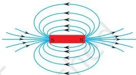
A magnetic field is the region around a magnet (or a current-carrying conductor) in which its force can be detected (NCERT, p. 196). You cannot see a field directly, so the chapter uses field lines — the path a free north pole would follow if placed in that field — to represent it on paper.
Two activities give you this pattern. In Activity 12.2, iron filings sprinkled around a bar magnet arrange themselves along curved lines once the board is tapped gently, because each filing becomes a tiny induced magnet and aligns with the field at its location.
In Activity 12.3, a compass is moved step by step around the magnet, marking the needle’s position each time; joining these points by a smooth curve traces one complete field line by hand.
Three properties of field lines come up repeatedly in CBSE questions:
- Direction: outside the magnet, field lines run from the north pole to the south pole; inside the magnet, they run from south to north, which is why the lines form closed loops (NCERT, p. 197). This direction is not arbitrary — it is defined as the direction a free compass needle’s north pole would move.
- Crowding shows strength: lines drawn closer together mean a stronger field at that point, because more field is packed into the same space near the poles.
- Lines never intersect: if two field lines crossed, a compass placed at that point would have to point in two directions at once, which is impossible (NCERT, p. 197).
Magnetic Field Around a Straight Wire, a Circular Loop, and a Solenoid
The field pattern around a current-carrying conductor depends on its shape.
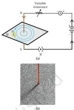
Straight wire: in Activity 12.5, iron filings sprinkled on a cardboard pierced by a vertical current-carrying wire settle into concentric circles centred on the wire. Increasing the current increases the compass deflection at a fixed point, showing the field gets stronger; moving the compass farther from the wire decreases the deflection, showing the field weakens with distance (NCERT, p. 198–199).
This is also why the circles in the diagram get wider apart as you move away from the wire — the same field “spreads out” over a larger circle, so it grows weaker per unit length.
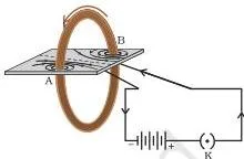
Circular loop: at the centre of a current-carrying loop, the arcs of the (very large) concentric circles look almost like straight lines, and every part of the loop contributes field in the same direction there.
This is why a coil of \(n\) turns produces a field \(n\) times as strong as a single turn carrying the same current — each turn’s contribution simply adds up in the same direction (NCERT, p. 200).
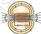
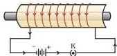
Solenoid: a solenoid is a coil of insulated copper wire wound closely in the shape of a cylinder. Its field pattern outside looks just like a bar magnet’s — one end behaves as a north pole, the other as a south pole.
Inside the solenoid, the field lines run as parallel straight lines, which means the field has the same strength at every point inside — it is uniform (NCERT, p. 201).
This uniformity holds through the middle of the coil; very close to the two open ends, the lines start to curve outward, so the field there is not the same as in the middle.
Right-Hand Thumb Rule vs Fleming’s Left-Hand Rule: Don’t Mix Them Up
These two rules answer two completely different questions, and mixing them up is the single most common error in this chapter.
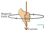
Right-hand thumb rule (also called Maxwell’s corkscrew rule): imagine gripping the current-carrying wire in your right hand with the thumb pointing in the direction of current. Your curled fingers then show the direction of the field lines circling the wire (NCERT, p. 199).
Use this rule only to find the magnetic field produced BY a current — there is no external field involved.
Fleming’s left-hand rule: stretch the thumb, forefinger and middle finger of your left hand so all three are mutually perpendicular. The forefinger points along the magnetic field, the middle finger along the current, and the thumb then points along the force (or motion) on the conductor (NCERT, p. 202–203).
Use this rule only when a current-carrying conductor is placed inside a separate, external magnetic field — it finds a force, not a field.
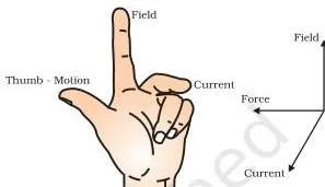
The confusion happens because both rules involve fingers and a current. The fix is to ask one question first: am I looking for the field a current produces (right hand), or the force a field exerts on a current (left hand)?
Electromagnets and Where the Magnetic Effect Is Used
Placing a soft-iron core inside a current-carrying solenoid magnetises the core strongly as long as current flows — this combination is called an electromagnet (NCERT, p. 201). Unlike a permanent magnet, its strength can be switched on and off, which is exactly why it is useful in devices like electric bells, cranes, and relays.
The same current-plus-field idea appears in the electric motor, electric generator, loudspeaker and microphone (NCERT, p. 203). A less obvious example is medical: nerve impulses in the human body are tiny electric currents, and they produce very weak magnetic fields — about one-billionth of the earth’s own field.
Magnetic Resonance Imaging (MRI) uses magnetic fields produced by the body (mainly around the heart and brain) to build diagnostic images (NCERT, p. 204). If a question asks you to “give an example of the magnetic effect in daily life outside electrical machines,” MRI is a ready answer.
Force on a Current-Carrying Conductor: The Basis of the Electric Motor
Activity 12.7 suspends a small aluminium rod between the poles of a horseshoe magnet, with the field pointing upward, and passes a current through the rod. The rod visibly jumps sideways — a force acts on it purely because it is carrying current inside a magnetic field.
Reverse the current alone, and the rod jumps the opposite way; reverse the magnet’s poles alone (keeping the same current direction), and it again jumps the opposite way (NCERT, p. 202).
This tells you the force depends on three things: the current in the conductor, the strength of the field, and (as the follow-up question on page 203 asks you to reason out) the length of the conductor inside the field — increasing any one of these increases the force.
The force is largest when the current direction is exactly perpendicular to the field direction (NCERT, p. 202); at other angles, only part of the current “cuts across” the field effectively, so the push is weaker.
Domestic Electric Circuits: Live, Neutral, Earth Wires and Fuse Ratings
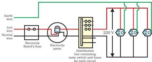
Every house supply carries three wires. The live wire (red insulation) and the neutral wire (black insulation) have a potential difference of 220 V between them in Indian households (NCERT, p. 204).
The earth wire (green insulation) is not part of the working circuit at all — it is a safety wire, connected to a metal plate buried in the ground, and it is wired to the metal body of appliances like an iron or a refrigerator.
| Wire | Insulation colour | Function |
|---|---|---|
| Live | Red | Carries current from the supply; 220 V relative to neutral |
| Neutral | Black | Completes the return path of the circuit |
| Earth | Green | Connects an appliance’s metal body to the ground; carries away leakage current so the body stays at earth potential and does not shock the user |
Homes usually run two separate circuits: a 15 A circuit for high-power appliances such as geysers and air coolers, and a 5 A circuit for lights and fans (NCERT, p. 204). A fuse in each circuit melts and breaks the connection if the current rises above what the wiring can safely carry, protecting both the appliance and the house wiring from overheating.
Two different faults can push current too high, and CBSE tests the difference between them directly: a short circuit happens when the live and neutral wires touch each other directly, usually because insulation has worn through, and the current jumps up abruptly.
Overloading happens when too many appliances are run from one socket at once, or when the supply voltage itself spikes — the current still rises, but there is no direct live-neutral contact causing it (NCERT, p. 204).
Rules and Relations to Remember (This Chapter Has No Algebraic Formula)
Unlike the Electricity chapter, Chapter 12 does not give you an equation to derive a numeric field or force value — it is built around three directional rules, plus one relation carried over from the previous chapter for domestic-circuit questions: \( P = VI \), where \(P\) is power in watts, \(V\) is potential difference in volts and \(I\) is current in amperes.
You need this relation to check whether an appliance’s current exceeds a circuit’s rated value.
| Rule name | What it finds | Hand / fingers used | When to apply |
|---|---|---|---|
| Right-hand thumb rule | Direction of the magnetic field around a current-carrying straight wire | Right hand, thumb along current, fingers curl | Straight conductor carrying current, no external field involved |
| Right-hand rule for a loop | Direction of the magnetic field at the centre of a current-carrying coil | Right hand curled in the direction of the current around the loop | Circular loop or solenoid, field inside or at the centre |
| Fleming’s left-hand rule | Direction of the force on a current-carrying conductor placed in an external magnetic field | Left hand: forefinger = field, middle finger = current, thumb = force | Conductor carrying current sits inside a separate magnetic field (motor effect) |
Worked Examples: New Numbers, Same Rules
Example A: Field direction for a wire carrying current from south to north
- Step 1: A straight horizontal wire carries current flowing from south to north. We want the direction of the magnetic field, viewed from each end of the wire.
- Step 2: Apply the right-hand thumb rule: grip the wire with the right hand, thumb pointing in the direction of current, i.e. from south to north.
- Step 3: The curled fingers give the field’s sense of rotation. Viewed from the end the current is leaving (the south end), the field circulates clockwise. Viewed from the end the current is arriving at (the north end), the field circulates anticlockwise — the same reasoning the textbook uses for an east-to-west current, just rotated to a south-to-north wire.
Final answer: The field circles clockwise when viewed from the south end, and anticlockwise when viewed from the north end.
Example B: Will a 1500 W geyser blow the fuse on a 5 A domestic circuit?
- Step 1: The geyser is rated 1500 W and runs on the standard 220 V domestic supply, on a circuit rated for a maximum of 5 A.
- Step 2: Use \( P = VI \), so the current drawn is \( I = \dfrac{P}{V} \).
\[ I = \frac{1500}{220} \approx 6.8\ \text{A} \]
Step 3: Compare this with the circuit’s rating: \( 6.8\ \text{A} \gt 5\ \text{A} \).
Final answer: The geyser draws about \(6.8\ \text{A}\), which exceeds the circuit’s 5 A rating, so the fuse will melt and break the circuit before the wiring can overheat.
Common Mistakes Students Make in Chapter 12
| Mistake | Correct rule | How to check your answer |
|---|---|---|
| Using the right hand for Fleming’s rule, or the left hand for the thumb rule | Field-finding always uses the right-hand thumb rule; force-finding always uses Fleming’s left-hand rule — the hands are never interchangeable | Ask first: am I finding a field (right hand) or a force (left hand)? |
| Forgetting that conventional current is opposite to electron flow | Current direction is always taken opposite to the direction electrons actually move (used directly in Example 12.2, NCERT p. 203) | Before applying Fleming’s rule to an electron or proton beam, reverse the arrow to get the current direction first |
| Assuming the solenoid’s field weakens gradually all along its length | The field is uniform through the middle of the solenoid; it only changes very close to the two open ends (NCERT, p. 201) | Check Fig. 12.10 — parallel straight lines run through the centre, and only the end regions show curving lines |
| Mixing up the live (red) and earth (green) wire colours | Live = red, Neutral = black, Earth = green (NCERT, p. 204) | Remember the earth wire never carries current normally — it only activates during a fault |
| Treating short circuit and overloading as the same fault | Short circuit = live and neutral touching directly; overloading = too many appliances or a voltage surge drawing more current than the rating allows (NCERT, p. 204) | Ask what caused the excess current — direct wire contact, or too much load |
How CBSE Frames Questions from This Chapter
The nine end-chapter exercise questions cover every question type CBSE uses for this chapter, so revising against them tells you exactly where to spend time.
| Q. No. | Type | What it tests | What a full-marks answer needs |
|---|---|---|---|
| 1 | MCQ | Field pattern near a long straight wire | Choose “concentric circles centred on the wire”; be ready to justify with the right-hand thumb rule |
| 2 | MCQ | Current behaviour during a short circuit | Choose “increases heavily”; explain that resistance drops sharply when live and neutral touch |
| 3 | True/False (2 parts) | Field at the centre of a coil; wire colour identification | (a) True — the field lines at a large coil’s centre are nearly parallel straight lines; (b) False — green is the earth wire, red is live |
| 4 | Short answer | Methods of producing a magnetic field | Name two: a permanent magnet, and a current-carrying conductor (straight wire, loop or solenoid) |
| 5 | Short reasoning | Condition for maximum force on a conductor | State that the force is largest when the current direction is perpendicular to the field direction |
| 6 | Applied direction-finding | Electron beam deflected by a magnetic field | Reverse the electron’s direction of motion to get the conventional current direction first, then apply Fleming’s left-hand rule |
| 7 | Rule-statement (3 parts) | All directional rules of the chapter in one answer | State the right-hand thumb rule for field around a wire, and Fleming’s left-hand rule for force on a conductor; part (iii), on the rule for current induced by a rotating coil, belongs to the electromagnetic induction portion of this chapter |
| 8 | Short answer | Definition of a short circuit | State that it happens when live and neutral wires touch directly, causing a sudden rise in current |
| 9 | Short reasoning | Function of the earth wire | Explain it gives a low-resistance path to the ground for leakage current, keeping the appliance body at earth potential so the user is not shocked |
Notice that diagram-based and rule-statement answers (Q1, Q3, Q7) carry as much weight as the reasoning and numeric-style answers (Q5, Q6, Q9) — do not skip practising the rule statements just because they look like “easy” recall questions.
Reading the Chapter’s Key Diagrams
Reconstructing a diagram from memory is often worth more marks than a written statement in this chapter.
- Fig. 12.4 (field lines around a bar magnet): arrows must point out of the north pole and into the south pole, and lines should be drawn closer together near the poles than in the middle region.
- Fig. 12.6 (straight wire, concentric circles): the circles must grow larger and more spaced out as you move away from the wire — a common mistake is drawing evenly spaced rings, which is wrong.
- Fig. 12.13 (Fleming’s left-hand rule): the three fingers must be shown mutually perpendicular, and in an exam it helps to label each finger’s meaning (field, current, force/motion) right next to the diagram.
- Fig. 12.15 (domestic circuit): label live, neutral and earth separately, and mark the two current ratings, 5 A and 15 A, on their respective lines rather than leaving the diagram unlabelled.
Quick Revision Summary for Chapter 12
- A magnetic field is the region around a magnet or current-carrying conductor where its force can be detected; field lines represent it, run north to south outside a magnet, never cross, and are closer together where the field is stronger.
- A straight current-carrying wire produces concentric circular field lines that spread farther apart with distance; the field gets stronger with more current and weaker farther from the wire.
- A coil of \(n\) turns produces \(n\) times the field of a single turn because each turn’s field adds in the same direction at the centre.
- A solenoid’s field outside resembles a bar magnet’s; inside, the field is uniform because the field lines run parallel — except very close to the two ends.
- Right-hand thumb rule finds the field direction around a current-carrying wire; Fleming’s left-hand rule finds the force direction on a current inside an external field — different hands for different questions.
- An electromagnet is a soft-iron core magnetised by a current-carrying solenoid; it can be switched on and off, unlike a permanent magnet.
- Domestic supply carries live (red, 220 V), neutral (black) and earth (green) wires; a fuse melts to break the circuit if current rises too high, from either a short circuit or overloading.
For the next chapter in sequence, continue your revision with our notes on the Our Environment chapter, or return to the Class 10 hub for notes across other subjects.
Frequently Asked Questions on Magnetic Effects of Electric Current
Why does a compass needle get deflected near a current-carrying wire?
Because the current itself sets up a magnetic field around the wire (Oersted’s 1820 observation). This field exerts a force on the compass needle’s poles and turns it away from the direction it normally points in the earth’s field.
What is the difference between the right-hand thumb rule and Fleming’s left-hand rule?
The right-hand thumb rule uses the right hand to find the magnetic field produced around a current-carrying wire — thumb along the current, fingers curling in the field’s direction.
Fleming’s left-hand rule uses the left hand to find the force on a current-carrying conductor placed inside an external magnetic field — forefinger for field, middle finger for current, thumb for force. One finds a field; the other finds a force, and they use opposite hands.
Why is the magnetic field inside a solenoid uniform?
Because the field lines inside a solenoid run as parallel straight lines, which means the field has the same strength and direction at every point through the middle of the coil. This uniformity does not extend to the very ends, where the lines begin to curve outward.
Which wire is the earth wire in a domestic circuit and why is it green?
The earth wire has green insulation and is connected to a metal plate buried in the ground. It is wired to the metal body of appliances so that any current leaking to the body flows safely into the earth instead of through a person who touches the appliance.
What is the difference between a short circuit and overloading?
A short circuit occurs when the live and neutral wires touch each other directly, usually because insulation has worn away, causing a sudden sharp rise in current. Overloading occurs when too many appliances are connected to one circuit, or the supply voltage spikes, drawing more current than the circuit’s rated value without any direct wire contact.
Does the direction of magnetic force on a current-carrying conductor reverse if the current is reversed?
Yes. Reversing either the current direction alone, or the magnetic field direction alone, reverses the direction of the force on the conductor. If both are reversed together, the force direction stays the same as before.
Reference: NCERT Class 10 Science textbook, chapter Magnetic Effects of Electric Current.
Explore Class 10 Science Notes
More for this chapter:
Related chapters: