This page collects the alternating current class 12 formulas from NCERT Physics Part I, Chapter 7, in one place. You will find the ac voltage and current equations for resistors, inductors and capacitors, rms values, impedance and phase angle of series LCR circuits, resonance, average power and power factor, and the transformer voltage and current ratios.
Each formula is grouped by topic, with the meaning and unit of every symbol, a “when to use it” line, and three worked examples with original numbers. All formulas come from the NCERT Class 12 Physics Part I textbook, Chapter 7, which you can verify on the official NCERT website.
For the full explanations and derivations, browse the Class 12 Physics formulas section or the Physics formulas index.
Formulas at a Glance
Every formula on this sheet in one table. The meaning of each symbol is in the symbol table, and the conditions for using each formula are in When to Use Each Formula.
| Purpose (what you are finding) | Formula |
|---|---|
| Instantaneous ac voltage | \( v = v_m \sin \omega t \) |
| Current in a pure resistor | \( i = i_m \sin \omega t, \quad i_m = \dfrac{v_m}{R} \) |
| rms current from peak current | \( I = \dfrac{i_m}{\sqrt{2}} = 0.707\, i_m \) |
| rms voltage from peak voltage | \( V = \dfrac{v_m}{\sqrt{2}} = 0.707\, v_m \) |
| Ohm’s law using rms values | \( V = IR \) |
| Average power in a resistor | \( P = VI = I^2R = \dfrac{V^2}{R} \) |
| Inductive reactance | \( X_L = \omega L = 2\pi\nu L \) |
| Current amplitude in a pure inductor | \( i_m = \dfrac{v_m}{X_L} \) |
| Capacitive reactance | \( X_C = \dfrac{1}{\omega C} = \dfrac{1}{2\pi\nu C} \) |
| Current amplitude in a pure capacitor | \( i_m = \dfrac{v_m}{X_C} \) |
| Impedance of a series LCR circuit | \( Z = \sqrt{R^2 + (X_C – X_L)^2} \) |
| Current amplitude in a series LCR circuit | \( i_m = \dfrac{v_m}{Z} \) |
| Phase angle between voltage and current | \( \tan \phi = \dfrac{X_C – X_L}{R} \) |
| Resonant angular frequency | \( \omega_0 = \dfrac{1}{\sqrt{LC}} \) |
| Resonant frequency in hertz (from \( \omega_0 \)) | \( \nu_r = \dfrac{\omega_0}{2\pi} \) |
| Average power in any ac circuit | \( P = VI \cos \phi \) |
| Power factor | \( \cos \phi = \dfrac{R}{Z} \) |
| Quality factor of a series LCR circuit | \( Q = \dfrac{\omega_0 L}{R} = \dfrac{1}{\omega_0 CR} \) |
| Transformer voltage ratio (ideal) | \( \dfrac{V_s}{V_p} = \dfrac{N_s}{N_p} \) |
| Transformer current ratio (ideal) | \( \dfrac{I_s}{I_p} = \dfrac{N_p}{N_s} \) |
All Alternating Current Class 12 Formulas, Grouped by Topic
AC Voltage Applied to a Resistor
For a pure resistor, the voltage and current are in phase — they reach zero, minimum and maximum at the same instants (NCERT, p. 178).
\[ v = v_m \sin \omega t \]
\[ i = i_m \sin \omega t, \qquad i_m = \frac{v_m}{R} \]
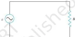
The instantaneous power \( p = i^2R \) is always positive, and its average over a cycle is
\[ \bar{p} = \frac{1}{2} i_m^2 R = I^2R = VI = \frac{V^2}{R} \]
rms Values of Current and Voltage
The rms (root mean square) current is the equivalent dc current that produces the same average heating in a resistor. It makes ac equations look exactly like dc equations (NCERT, p. 179).
\[ I = \frac{i_m}{\sqrt{2}} = 0.707\, i_m \]
\[ V = \frac{v_m}{\sqrt{2}} = 0.707\, v_m \]
\[ V = IR \]
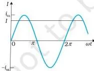
The household 220 V supply is an rms value; its peak is \( v_m = \sqrt{2} \times 220 = 311\ \)V.
AC Voltage Applied to an Inductor
In a purely inductive circuit the current lags the voltage by \( \pi/2 \) (one-quarter cycle), and the average power over a complete cycle is zero (NCERT, p. 182).
\[ i = i_m \sin\left(\omega t – \frac{\pi}{2}\right), \qquad i_m = \frac{v_m}{X_L} \]
\[ X_L = \omega L = 2\pi\nu L \]
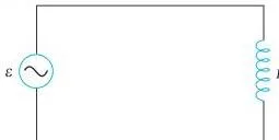
The quantity \( X_L \) is the inductive reactance; it limits current the way resistance does, and it grows with frequency.
AC Voltage Applied to a Capacitor
In a purely capacitive circuit the current leads the voltage by \( \pi/2 \), and the average power over a complete cycle is zero (NCERT, p. 184).
\[ i = i_m \sin\left(\omega t + \frac{\pi}{2}\right), \qquad i_m = \frac{v_m}{X_C} \]
\[ X_C = \frac{1}{\omega C} = \frac{1}{2\pi\nu C} \]
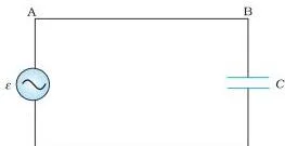
The capacitive reactance \( X_C \) falls as frequency rises, so a capacitor passes high-frequency current more easily.
AC Voltage Applied to a Series LCR Circuit
In a series LCR circuit the same current flows through R, L and C. The total opposition is the impedance \( Z \), and the phase angle between source voltage and current is \( \phi \) (NCERT, p. 187).
\[ i = i_m \sin(\omega t + \phi) \]
\[ i_m = \frac{v_m}{\sqrt{R^2 + (X_C – X_L)^2}} = \frac{v_m}{Z} \]
\[ Z = \sqrt{R^2 + (X_C – X_L)^2} \]
\[ \tan \phi = \frac{X_C – X_L}{R} \]
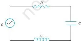
The voltage amplitudes across the elements are \( v_{Rm} = i_m R \), \( v_{Cm} = i_m X_C \) and \( v_{Lm} = i_m X_L \). The phasor diagram below shows why \( V_R \) and \( V_C \) cannot be added as ordinary numbers.
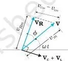
If \( X_C \gt X_L \), \( \phi \) is positive and the current leads the source voltage. If \( X_C \lt X_L \), \( \phi \) is negative and the current lags.
Resonance
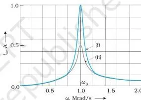
At the resonant frequency, the inductive and capacitive reactances cancel, so the impedance is minimum and the current is maximum (NCERT, p. 188–189).
\[ \omega_0 = \frac{1}{\sqrt{LC}} \]
\[ \nu_r = \frac{\omega_0}{2\pi} \]
At resonance: \( X_C = X_L \), \( Z = R \) (minimum), \( i_m = v_m/R \) (maximum) and \( \cos\phi = 1 \). Resonance needs both L and C in the circuit — an RL or RC circuit cannot resonate. The sharpness of the resonance is measured by the quality factor (NCERT, p. 198):
\[ Q = \frac{\omega_0 L}{R} = \frac{1}{\omega_0 CR} \]
Power in AC Circuit: The Power Factor
The average power over a cycle depends on the phase angle through the power factor \( \cos\phi \) (NCERT, p. 191):
\[ P = VI \cos\phi = I^2 Z \cos\phi \]
\[ \cos\phi = \frac{R}{Z} \]
- Pure resistor: \( \phi = 0 \), \( \cos\phi = 1 \), maximum power \( P = VI \).
- Pure inductor or capacitor: \( \cos\phi = 0 \), zero average power — the current is called wattless current.
- Series LCR: power is dissipated only in the resistor, \( P = I^2R \).
- At resonance: \( \cos\phi = 1 \), so \( P = I^2R \), the maximum possible for that current.
Transformers
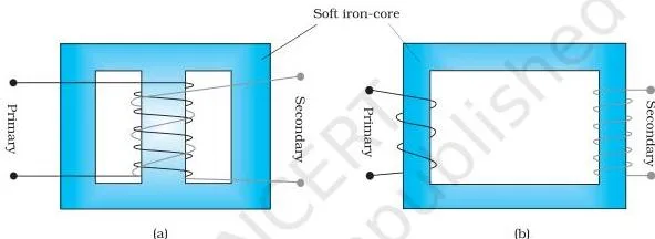
A transformer works by mutual induction: the alternating flux \( \phi \) links both coils, inducing emfs \( \varepsilon_s = -N_s\, d\phi/dt \) and \( \varepsilon_p = -N_p\, d\phi/dt \) (NCERT, p. 194). For an ideal transformer (NCERT, p. 195):
\[ \frac{v_s}{v_p} = \frac{N_s}{N_p} \]
\[ \frac{i_p}{i_s} = \frac{N_s}{N_p} \]
\[ V_s = \left(\frac{N_s}{N_p}\right) V_p, \qquad I_s = \left(\frac{N_p}{N_s}\right) I_p \]
Power in equals power out: \( i_p v_p = i_s v_s \). If \( N_s \gt N_p \) it is a step-up transformer (voltage up, current down); if \( N_s \lt N_p \) it is a step-down transformer.
What Each Symbol Means
| Symbol | What it means | Unit |
|---|---|---|
| \( v, v_m \) | instantaneous voltage and peak voltage (amplitude) of the ac source | V (volt) |
| \( i, i_m \) | instantaneous current and peak current (amplitude) | A (ampere) |
| \( V, I \) | rms voltage and rms current | V, A |
| \( \omega \) | angular frequency of the ac source | rad/s |
| \( \nu \) | frequency of the ac source | Hz |
| \( R \) | resistance | \( \Omega \) (ohm) |
| \( L \) | self-inductance of the inductor | H (henry) |
| \( C \) | capacitance of the capacitor | F (farad) |
| \( X_L \) | inductive reactance \( \omega L \) | \( \Omega \) |
| \( X_C \) | capacitive reactance \( 1/\omega C \) | \( \Omega \) |
| \( Z \) | impedance of the circuit | \( \Omega \) |
| \( \phi \) | phase angle between the source voltage and the current | rad (or degree) |
| \( \cos\phi \) | power factor | dimensionless |
| \( P \) | average power over a cycle | W (watt) |
| \( \omega_0 \) | resonant angular frequency | rad/s |
| \( Q \) | quality factor of a series LCR circuit | dimensionless |
| \( N_p, N_s \) | number of turns in the primary and secondary coils | count (dimensionless) |
| \( v_p, v_s \) | primary and secondary voltages | V |
| \( i_p, i_s \) | primary and secondary currents | A |
| \( \phi \) (in transformer equations) | magnetic flux linking each turn of the coil | Wb (weber) |
| \( \varepsilon_s, \varepsilon_p \) | induced emf in the secondary and primary coils | V |
| \( q \) | charge on the capacitor | C (coulomb) |
When to Use Each Formula
| Formula | Use it when… |
|---|---|
| \( v = v_m \sin \omega t \) | the source voltage is sinusoidal and you need the instantaneous value or its peak \( v_m \). |
| \( I = i_m/\sqrt{2}, \; V = v_m/\sqrt{2} \) | converting peak values to the rms values that meters, ratings and the 220 V household supply actually state. |
| \( V = IR, \; P = I^2R = VI = V^2/R \) | the circuit is purely resistive — rms values behave exactly like dc values. |
| \( X_L = \omega L = 2\pi\nu L \) | a pure inductor opposes current; the reactance rises with frequency. |
| \( X_C = 1/\omega C = 1/(2\pi\nu C) \) | a pure capacitor opposes current; the reactance falls with frequency. |
| \( Z = \sqrt{R^2 + (X_C – X_L)^2} \) | finding the total opposition of any series LCR circuit. |
| \( \tan\phi = (X_C – X_L)/R \) | deciding whether the circuit is capacitive (\( \phi \gt 0 \), current leads) or inductive (\( \phi \lt 0 \), current lags). |
| \( \omega_0 = 1/\sqrt{LC} \) | finding the frequency at which impedance is minimum and current is maximum; requires both L and C present. |
| \( P = VI \cos\phi \) | average power in any ac circuit; \( \cos\phi \) is the power factor. |
| \( V_s/V_p = N_s/N_p, \; I_s/I_p = N_p/N_s \) | ideal transformer problems; step-up if \( N_s \gt N_p \), step-down if \( N_s \lt N_p \). |
Worked Examples
Example 1: Resistance, peak voltage and rms current of a bulb
A bulb is rated 60 W for a 220 V supply. Find (a) its resistance, (b) the peak voltage of the source, and (c) the rms current through it.
Step 1: The rating gives average power \( P = 60\ \)W at rms voltage \( V = 220\ \)V.
Use \( R = V^2/P \).
\[ R = \frac{(220\ \text{V})^2}{60\ \text{W}} = 806.7\ \Omega \]
Step 2: Convert rms voltage to peak voltage: \( v_m = \sqrt{2}\,V \).
\[ v_m = 1.414 \times 220\ \text{V} = 311\ \text{V} \]
Step 3: Find rms current from \( P = VI \).
\[ I = \frac{P}{V} = \frac{60\ \text{W}}{220\ \text{V}} = 0.273\ \text{A} \]
Final answer: \( R = 807\ \Omega \), \( v_m = 311\ \)V, \( I = 0.273\ \)A.
Example 2: Impedance, phase angle and power in a series LCR circuit
A series LCR circuit has \( R = 40\ \Omega \), \( L = 0.30\ \)H and \( C = 50\ \mu\)F, connected to a 230 V, 50 Hz ac source. Find the impedance, the phase angle, the power factor and the average power.
Step 1: Compute the two reactances at \( \nu = 50\ \)Hz.
\[ X_L = 2\pi\nu L = 2\pi(50)(0.30) = 94.2\ \Omega \]
\[ X_C = \frac{1}{2\pi\nu C} = \frac{1}{2\pi(50)(50 \times 10^{-6})} = 63.7\ \Omega \]
Step 2: Use the impedance formula for a series LCR circuit.
\[ Z = \sqrt{R^2 + (X_C – X_L)^2} = \sqrt{40^2 + (63.7 – 94.2)^2} = 50.4\ \Omega \]
Step 3: Phase angle and power factor.
Since \( X_L \gt X_C \), the current lags the voltage.
\[ \tan\phi = \frac{X_C – X_L}{R} = \frac{63.7 – 94.2}{40} = -0.763, \qquad \phi = -37.4^\circ \]
\[ \cos\phi = \frac{R}{Z} = \frac{40}{50.4} = 0.794 \]
Step 4: rms current, then average power.
\[ I = \frac{V}{Z} = \frac{230}{50.4} = 4.56\ \text{A} \]
\[ P = VI\cos\phi = 230 \times 4.56 \times 0.794 = 833\ \text{W} \]
Final answer: \( Z = 50.4\ \Omega \), \( \phi = -37.4^\circ \) (current lags), \( \cos\phi = 0.79 \), \( P = 833\ \)W. Check: \( I^2R = (4.56)^2 \times 40 = 832\ \)W — the two routes agree.
Example 3: Transformer voltage and current ratios
A transformer has 250 turns on the primary and 5000 turns on the secondary. The primary is connected to a 240 V ac supply and draws 2.0 A. Find the secondary voltage and secondary current.
Step 1: Secondary voltage from the turns ratio \( V_s = (N_s/N_p)V_p \).
\[ V_s = \frac{5000}{250} \times 240 = 4800\ \text{V} \]
Step 2: Secondary current — the turns ratio is inverted: \( I_s = (N_p/N_s)I_p \).
\[ I_s = \frac{250}{5000} \times 2.0 = 0.10\ \text{A} \]
Step 3: Energy check for the ideal transformer.
\[ V_p I_p = 240 \times 2.0 = 480\ \text{W}, \qquad V_s I_s = 4800 \times 0.10 = 480\ \text{W} \]
Final answer: \( V_s = 4800\ \)V, \( I_s = 0.10\ \)A. Power in equals power out, so the step-up does not create energy.
Common Mistakes to Avoid
| Mistake | Correct rule | How to check your answer |
|---|---|---|
| Adding \( V_R \) and \( V_C \) like ordinary numbers | They are \( \pi/2 \) out of phase, so \( V = \sqrt{V_R^2 + V_C^2} \) | The phasor sum must come out equal to the source voltage |
| Using rms values where peak values are needed, or vice versa | \( V = v_m/\sqrt{2} \) and \( v_m = \sqrt{2}\,V \) | Household 220 V is rms; its peak is 311 V |
| Writing that current leads in an inductor | Current lags voltage by \( \pi/2 \) in an inductor and leads by \( \pi/2 \) in a capacitor | Check the sign: \( \sin(\omega t – \pi/2) \) is lag, \( \sin(\omega t + \pi/2) \) is lead |
| Using \( \tan\phi = (X_L – X_C)/R \) | \( \tan\phi = (X_C – X_L)/R \) | If \( X_C \gt X_L \), \( \phi \) is positive and current leads |
| Inverting the transformer ratios | \( V_s/V_p = N_s/N_p \), but \( I_s/I_p = N_p/N_s \) | Power check: \( V_p I_p = V_s I_s \) |
| Treating a pure inductor or capacitor as a power consumer | Pure L and C take zero average power; only R dissipates energy | \( P = I^2R \); with no R in the circuit, \( P = 0 \) |
Frequently Asked Questions
Why is the household supply called 220 V when the voltage swings up to 311 V?
220 V is the rms value, defined so that it produces the same average heating as 220 V dc. The instantaneous voltage oscillates between \( +v_m \) and \( -v_m \), where \( v_m = \sqrt{2} \times 220 = 311\ \)V. Meters and appliance ratings always state rms values.
Why is the average power zero in a pure inductor or capacitor?
Because the phase difference between voltage and current is \( \pi/2 \), so \( \cos\phi = 0 \) and \( P = VI\cos\phi = 0 \). Energy is stored in the magnetic or electric field during one half-cycle and returned to the source during the next. This current is called wattless current.
What happens at resonance in a series LCR circuit?
At \( \omega_0 = 1/\sqrt{LC} \), the reactances cancel: \( X_C = X_L \). Then \( Z = R \) (minimum), the current is maximum (\( i_m = v_m/R \)), and \( \cos\phi = 1 \), so the power dissipated is maximum. Resonance requires both L and C in the circuit.
Does a step-up transformer violate conservation of energy?
No. The voltage is stepped up but the current is stepped down by the same ratio, so \( V_p I_p = V_s I_s \). In the worked example above, 240 V × 2.0 A = 4800 V × 0.10 A = 480 W on both sides.
Reference: NCERT Class 12 Physics textbook, chapter Alternating Current.
Explore Class 12 Physics Formulas
More for this chapter:
Class 12 Physics on LearnCBSE:
Related chapters: