
These alternating current class 12 notes compress NCERT Physics Part I Chapter 7 into the essentials for exam revision: rms values, reactance, phasors, series LCR circuits, resonance, power factor and transformers. Every definition and formula is here, with two fully worked numericals and an examiner-minded mark guide. Reference: NCERT Class 12 Physics Part I textbook, chapter 7, Alternating Current.
Use this page as your chapter recap or night-before-the-test refresher. For the full set, see the Class 12 Physics notes hub, the Class 12 notes index and the CBSE notes home. You can also verify any formula against the official NCERT textbook portal.
Why AC? The Chapter’s Roadmap
An alternating current changes direction with time, unlike direct current. The mains supply at home is an alternating voltage that varies as a sine function of time — in India it alternates at 50 Hz (NCERT, p. 177–178).
Two reasons make ac the standard for power distribution (NCERT, p. 177):
- Easy voltage conversion — ac voltages can be stepped up or down efficiently with transformers.
- Economical long-distance transmission — high voltage means lower current, which cuts resistive losses.
History explains this: the Tesla–Westinghouse ac system beat Edison’s dc in the “war of the currents” precisely because ac could be transformed and dc could not (NCERT, p. 179).
Each section below builds on the last, in the teaching order a teacher would use: resistor → rms value → phasors → inductor → capacitor → series LCR → resonance → power factor → transformer.
Resistor in an AC Circuit: Phase, Power and the rms Value
Start with a pure resistor connected to a sinusoidal source. The source voltage is (NCERT, p. 178):
\[ v = v_m \sin \omega t \]
where \( v_m \) is the amplitude (peak value) and \( \omega \) is the angular frequency.
Apply Kirchhoff’s loop rule \( v_m \sin \omega t = iR \). Since \( R \) is constant, the current is (NCERT, p. 178):
\[ i = \frac{v_m}{R} \sin \omega t = i_m \sin \omega t, \qquad i_m = \frac{v_m}{R} \]
This is Ohm’s law working for ac exactly as for dc. Both \( v \) and \( i \) reach zero, minimum and maximum at the same instants — voltage and current are in phase in a pure resistor.
The “average current is zero” trap
The sum of instantaneous current values over one full cycle is zero, so the average current is zero. But power depends on \( i^2 \), which is always positive (NCERT, p. 178):
\[ p = i^2R = i_m^2 R \sin^2 \omega t \]
The average of \( \sin^2 \omega t \) over a cycle is \( 1/2 \), so a resistor still dissipates energy:
\[ \bar{p} = \frac{1}{2} i_m^2R \]
Root mean square (rms) values
To write ac power in the same form as dc power \( P = I^2R \), define the rms (effective) current as the dc current that would produce the same heating in a resistor (NCERT, p. 180):
\[ I = \frac{i_m}{\sqrt{2}} = 0.707\, i_m, \qquad V = \frac{v_m}{\sqrt{2}} = 0.707\, v_m \]
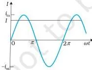
With rms values, everything takes the dc form: \( P = I^2R = VI = V^2/R \) (NCERT, p. 180).
Exam habit: appliance and mains ratings are always rms. A 220 V (rms) supply has peak \( v_m = \sqrt{2} \times 220 = 311\ \text{V} \).
Phasors: Reading AC Circuits as Rotating Vectors
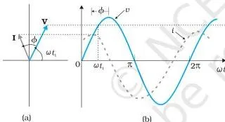
A phasor is a vector that rotates anticlockwise about the origin with angular speed \( \omega \) (NCERT, p. 181). Its length represents the amplitude (peak value), and its vertical projection gives the instantaneous value at that moment.
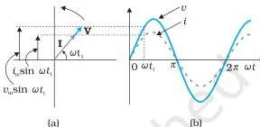
Taking the vertical projections of the phasors \( \mathbf{V} \) and \( \mathbf{I} \) regenerates the sine curves of \( v \) and \( i \). In a resistor the two phasors stay parallel at all times, which is exactly why the phase angle is zero.
Honest caveat: voltages and currents are scalars, not vectors. Phasors are only a convenient addition rule — harmonically varying scalars combine in the same way as the projections of rotating vectors, so we borrow vector addition (NCERT, p. 181, footnote).
The same rotating picture runs through the whole chapter: the inductor is a current phasor \( \pi/2 \) behind, the capacitor \( \pi/2 \) ahead, and the series LCR circuit is a triangle of three phasors. If you can read which phasor leads, you can read any ac circuit.
Inductor and Capacitor in AC: Reactance and Phase
These two elements introduce the idea of reactance — an opposition to current that plays the role of resistance but consumes no power on average.
Inductor: current lags voltage by \( \pi/2 \)
Kirchhoff’s loop rule for a purely inductive circuit is \( v – L\, di/dt = 0 \), where the second term is the self-induced Faraday emf (the negative sign follows from Lenz’s law — revise it with the electromagnetic induction notes before this section). Integrating gives (NCERT, p. 182):
\[ i = i_m \sin\left(\omega t – \frac{\pi}{2}\right), \qquad i_m = \frac{v_m}{X_L} \]
The inductive reactance is \( X_L = \omega L = 2\pi \nu L \), measured in ohm (NCERT, p. 182). It grows with both inductance and frequency.
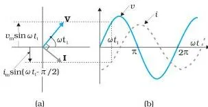
Capacitor: current leads voltage by \( \pi/2 \)
With a capacitor, \( v = q/C \) and \( i = dq/dt \), which gives (NCERT, p. 184):
\[ i = i_m \sin\left(\omega t + \frac{\pi}{2}\right), \qquad i_m = \frac{v_m}{X_C} \]
The capacitive reactance is \( X_C = 1/(\omega C) = 1/(2\pi \nu C) \), also in ohm (NCERT, p. 184). It shrinks when frequency rises.
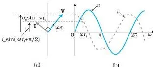
Average power is zero for both
The instantaneous power supplied to an inductor is \( p_L = -\frac{i_m v_m}{2} \sin(2\omega t) \), whose average over a full cycle is zero because the average of \( \sin(2\omega t) \) is zero (NCERT, p. 183). The capacitor behaves identically (NCERT, p. 185).
Neither element dissipates energy — each stores it in one half cycle and returns it to the source in the other.
Real-life application: the tubelight choke
A choke is an inductor placed in series with a tubelight to limit the current. It does this through reactance, which stores and returns energy instead of burning it as heat the way a resistor would. A real choke still warms a little because its winding has resistance.
Two NCERT qualitative experiments, shortened
- Lamp with a capacitor: on dc the lamp does not glow after charging; on ac it glows, and grows dimmer when \( C \) is reduced because \( X_C = 1/(\omega C) \) rises (NCERT, p. 185, Example 7.3).
- Iron rod into an inductor coil: the bulb dims because the iron raises the coil’s inductance, so \( X_L \) increases and more voltage drops across the inductor, leaving less for the bulb (NCERT, p. 185, Example 7.5).
Comparison: R, L and C in an ac circuit
| Element | Phase of current vs voltage | Opposition formula | Frequency dependence | Average power |
|---|---|---|---|---|
| Resistor | in phase (\( \phi = 0 \)) | \( R \) (resistance) | none | \( I^2R \), dissipated as heat |
| Inductor | current lags by \( \pi/2 \) | \( X_L = \omega L \) | rises with frequency | zero (stores and returns) |
| Capacitor | current leads by \( \pi/2 \) | \( X_C = 1/(\omega C) \) | falls with frequency | zero (stores and returns) |
Memory device — ELI the ICE man. In an L (inductor), E (voltage) leads I (current). In a C (capacitor), I (current) leads E (voltage). “ELI” and “ICE” give the two orders.
Series LCR Circuit: Impedance, Phase Angle and Resonance
Now combine R, L and C in series. The same current flows through all three elements, so it has the same amplitude and phase everywhere: \( i = i_m \sin(\omega t + \phi) \) (NCERT, p. 187).
The phasor triangle
Draw the three voltage phasors: \( \mathbf{V_R} \) is parallel to \( \mathbf{I} \), \( \mathbf{V_L} \) is \( \pi/2 \) ahead, and \( \mathbf{V_C} \) is \( \pi/2 \) behind (NCERT, p. 187). The source voltage is their vector sum:
\[ \mathbf{V_L} + \mathbf{V_R} + \mathbf{V_C} = \mathbf{V} \]
Because \( \mathbf{V_L} \) and \( \mathbf{V_C} \) point in opposite directions along the same line, they combine into a single phasor of magnitude \( |v_{Cm} – v_{Lm}| \). Pythagoras then gives (NCERT, p. 187):
\[ v_m^2 = (i_m R)^2 + (i_m X_C – i_m X_L)^2 \]
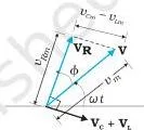
Define the impedance \( Z \) — the total opposition to current (NCERT, p. 187):
\[ Z = \sqrt{R^2 + (X_C – X_L)^2}, \qquad i_m = \frac{v_m}{Z} \]
The phase angle \( \phi \) between source voltage and current is (NCERT, p. 188):
\[ \tan \phi = \frac{X_C – X_L}{R} \]
Two nature rules
- \( X_C \gt X_L \) → \( \phi \) positive → current leads voltage → circuit is predominantly capacitive.
- \( X_C \lt X_L \) → \( \phi \) negative → current lags voltage → circuit is predominantly inductive.
Resonance
At one particular angular frequency, the inductive and capacitive reactances cancel exactly (NCERT, p. 189):
\[ X_L = X_C \quad \Rightarrow \quad \omega_0 = \frac{1}{\sqrt{LC}} \]
At resonance the impedance drops to its minimum \( Z = R \), so the current is a maximum \( i_m = v_m/R \).
Critical point: resonance needs both L and C. Only then do the voltages across them cancel (they are out of phase); an RL or RC circuit cannot resonate (NCERT, p. 189).
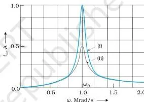
The sharpness of the peak is set by the quality factor \( Q = \omega_0 L/R = 1/(\omega_0 CR) \) (NCERT, p. 198). A smaller R means a larger Q, hence a sharper, more selective response.
Applications
- Radio / TV tuning: varying the tuning capacitor changes the resonant frequency until it matches the desired station’s signal, making the current amplitude for that station maximum (NCERT, p. 189).
- Airport metal detector: a coil tuned to resonance is disturbed by metal on the body, changing the circuit’s impedance and current, which triggers the alarm (NCERT, p. 193, Example 7.10).
Resonant circuits also connect this chapter to the next: the electromagnetic oscillations in LC circuits are what you will study next in the electromagnetic waves notes.
Power in AC Circuits and the Power Factor
For a series LCR circuit driven by \( v = v_m \sin \omega t \), the instantaneous power is \( p = vi \). Averaging over a cycle kills the time-dependent cosine term, leaving (NCERT, p. 190):
\[ P = VI \cos \phi, \qquad \text{also written} \quad P = I^2 Z \cos \phi \]
The power factor is \( \cos \phi \) — the cosine of the phase angle between source voltage and current. It measures how close the circuit is to expending the maximum power (NCERT, p. 199).
The four cases
- Pure resistor: \( \phi = 0 \), \( \cos \phi = 1 \) — maximum power dissipation (NCERT, p. 191).
- Pure inductor or capacitor: \( \cos \phi = 0 \) — zero power despite current flowing; this current is the wattless current (NCERT, p. 191).
- Series LCR (off resonance): power is dissipated only in the resistor, \( P = I^2R \) (NCERT, p. 191).
- At resonance: \( X_L = X_C \), \( \phi = 0 \), \( \cos \phi = 1 \), so \( P = I^2R \) is maximum (NCERT, p. 191).
Why a low power factor wastes transmission power
To deliver a given power \( P = IV\cos\phi \) at a fixed voltage, a small \( \cos \phi \) forces a larger current, and the transmission loss grows as \( I^2R \). The fix is to connect a capacitor of the right value in parallel: its leading wattless current cancels the circuit’s lagging wattless current, pulling \( \cos \phi \) toward 1 (NCERT, p. 191, Example 7.7).
Transformer: Turn Ratio, Step-Up and Step-Down
A transformer changes an alternating voltage from one value to another using the principle of mutual induction (NCERT, p. 194). Two insulated coils are wound on a soft-iron core: the primary coil with \( N_p \) turns (input) and the secondary coil with \( N_s \) turns (output).
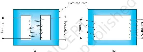
The ideal-transformer relations rest on three assumptions: negligible primary resistance and current, negligible flux leakage (nearly all flux links both coils), and small secondary current (NCERT, p. 195).
The two ratio laws
The induced emfs are proportional to the turns: \( v_s/v_p = N_s/N_p \). Assuming 100% efficiency — power in equals power out — the current ratio is the inverse (NCERT, p. 195):
\[ \frac{V_s}{V_p} = \frac{N_s}{N_p}, \qquad \frac{I_s}{I_p} = \frac{N_p}{N_s} \]
- Step-up: \( N_s \gt N_p \) → \( V_s \gt V_p \), but \( I_s \lt I_p \).
- Step-down: \( N_s \lt N_p \) → \( V_s \lt V_p \), but \( I_s \gt I_p \).
Why no energy violation: when the voltage steps up, the current steps down in the same proportion, so \( i_p v_p = i_s v_s \) and power is conserved (NCERT, p. 199).
Four real energy losses
- Flux leakage — not all primary flux links the secondary; reduced by winding the coils one over the other.
- Winding resistance — \( I^2R \) heating in the wire; minimised by using thick wire in high-current windings.
- Eddy currents — induced in the iron core by the alternating flux; reduced by laminating the core.
- Hysteresis — repeated magnetisation reversal heats the core; reduced with a low-hysteresis-loss magnetic material.
These four are why real transformers fall below 100% efficiency, though well-designed ones exceed 95% (NCERT, p. 195).
The transmission chain
Generator → step-up transformer (current drops, so \( I^2R \) loss falls) → long-distance transmission lines → step-down at area substations → further step-down at distribution substations and utility poles → 240 V at home (NCERT, p. 196).
Key Terms in AC Circuits: Quick-Reference Definitions
Fix the vocabulary with this one-table glossary. The example column uses concrete values so each term has a number attached, not just a phrase.
| Term | Plain meaning | Concrete example |
|---|---|---|
| Alternating voltage | Voltage that varies sinusoidally with time | Mains supply \( v = v_m \sin \omega t \) at 50 Hz |
| Alternating current | Current driven by an alternating voltage; reverses direction each half cycle | Current in any household appliance |
| Amplitude (peak value) | Maximum value of the oscillating voltage or current | \( v_m = 311\ \text{V} \) for a 220 V supply |
| Angular frequency | \( \omega = 2\pi\nu \), rate of phase change | \( \omega = 2\pi \times 50 \approx 314\ \text{rad/s} \) |
| rms (effective) current | dc current that produces the same heating in a resistor | \( I = i_m/\sqrt{2} = 0.707\, i_m \) |
| rms (effective) voltage | dc voltage giving the same heating as the ac | 220 V mains means \( V = 220\ \text{V} \), peak \( v_m = 311\ \text{V} \) |
| Inductive reactance | Opposition to current from an inductor | \( X_L = \omega L = 2\pi\nu L \), in ohm |
| Capacitive reactance | Opposition to current from a capacitor | \( X_C = 1/(\omega C) = 1/(2\pi\nu C) \), in ohm |
| Impedance | Total opposition to ac current from R, L and C together | \( Z = \sqrt{R^2 + (X_C – X_L)^2} \), in ohm |
| Phase angle | Angle by which current leads or lags the source voltage | \( \tan \phi = (X_C – X_L)/R \) |
| Power factor | \( \cos \phi \), fraction of maximum possible power used | \( \cos \phi = R/Z \), ranges 0 to 1 |
| Wattless current | Current flow with zero average power, due to 90° phase shift | Current in a pure inductor or capacitor |
| Resonance | State where \( X_L = X_C \), giving minimum impedance and maximum current | \( \omega_0 = 1/\sqrt{LC} \), \( Z = R \), \( I = V/R \) |
| Quality factor | Measures sharpness of the resonance peak | \( Q = \omega_0 L/R = 1/(\omega_0 CR) \), dimensionless |
| Step-up / step-down transformer | Raises / lowers voltage while conserving power | \( V_s/V_p = N_s/N_p \); \( N_s \gt N_p \) = step-up |
Alternating Current Class 12 Notes: Formula Sheet
Every equation you need for numericals, with symbol meanings and SI units — the night-before list.
| Quantity | Formula | Symbol meanings | SI unit |
|---|---|---|---|
| Source voltage | \( v = v_m \sin \omega t \) | \( v_m \) = amplitude, \( \omega \) = angular frequency | V |
| rms relations | \( I = i_m/\sqrt{2} \), \( V = v_m/\sqrt{2} \) | \( i_m, v_m \) = peak values | A, V |
| Resistor (rms form) | \( I = V/R \), \( P = VI = I^2R = V^2/R \) | \( R \) = resistance | Ω, W |
| Inductive reactance | \( X_L = \omega L = 2\pi \nu L \) | \( L \) = inductance, \( \nu \) = frequency | Ω |
| Capacitive reactance | \( X_C = 1/(\omega C) = 1/(2\pi \nu C) \) | \( C \) = capacitance | Ω |
| Impedance (series LCR) | \( Z = \sqrt{R^2 + (X_C – X_L)^2} \) | \( X_C – X_L \) = net reactance | Ω |
| Phase angle | \( \tan \phi = (X_C – X_L)/R \) | \( \phi \) between \( v \) and \( i \) | rad or ° |
| Resonant frequency | \( \omega_0 = 1/\sqrt{LC} \) | frequency where \( X_L = X_C \) | rad/s |
| Average power | \( P = VI \cos \phi \) | \( \cos \phi \) = power factor | W |
| Power factor | \( \cos \phi = R/Z \) | — | dimensionless |
| Quality factor | \( Q = \omega_0 L/R = 1/(\omega_0 CR) \) | sharpness of resonance | dimensionless |
| Transformer voltage ratio | \( V_s/V_p = N_s/N_p \) | \( N_s, N_p \) = secondary, primary turns | — |
| Transformer current ratio | \( I_s/I_p = N_p/N_s \) | inverse of turns ratio | — |
Worked Examples: LCR and Transformer Numericals Step by Step
Every series LCR numerical follows the same five steps. State the method before substituting — it earns method marks and keeps your algebra straight:
- Compute the inductive reactance \( X_L = 2\pi\nu L \).
- Compute the capacitive reactance \( X_C = 1/(2\pi\nu C) \).
- Combine with R into the impedance \( Z = \sqrt{R^2 + (X_C – X_L)^2} \).
- Find the phase angle \( \tan \phi = (X_C – X_L)/R \) and name the circuit.
- Calculate current \( I = V/Z \) and power \( P = VI\cos\phi \) (or \( I^2R \)).
Example A: Series LCR circuit (original numbers)
A series LCR circuit with \( R = 30\ \Omega \), \( L = 0.50\ \text{H} \) and \( C = 50\ \mu\text{F} \) is connected to a 100 V, 50 Hz ac source. Find the impedance, the phase angle, the current and the power.
- Step 1: Inductive reactance \( X_L = 2\pi\nu L = 2 \times 3.14 \times 50 \times 0.50 = 157\ \Omega \).
- Step 2: Capacitive reactance \( X_C = \frac{1}{2\pi\nu C} = \frac{1}{2 \times 3.14 \times 50 \times 50 \times 10^{-6}} = 63.7\ \Omega \).
- Step 3: Impedance \( Z = \sqrt{R^2 + (X_L – X_C)^2} = \sqrt{30^2 + (157 – 63.7)^2} = \sqrt{900 + 93.3^2} \approx 98.0\ \Omega \).
- Step 4: Phase angle \( \tan \phi = \frac{X_C – X_L}{R} = \frac{63.7 – 157}{30} = -3.11 \), so \( \phi \approx -72^\circ \).
Negative \( \phi \) means current lags voltage — the circuit is predominantly inductive.
- Step 1: Current \( I = \frac{V}{Z} = \frac{100}{98.0} \approx 1.02\ \text{A} \).
- Step 2: Power factor \( \cos \phi = \frac{R}{Z} = \frac{30}{98.0} \approx 0.31 \).
Power \( P = VI\cos\phi = 100 \times 1.02 \times 0.31 \approx 31\ \text{W} \).
Check: \( P = I^2R = (1.02)^2 \times 30 \approx 31\ \text{W} \) — the two routes agree, confirming the answer.
Example B: Step-up transformer (original numbers)
A step-up transformer has 400 primary turns and 2000 secondary turns, a primary supply of 200 V, and a secondary current of 4.0 A. Find the secondary voltage, the primary current, and verify energy conservation.
Step 1: Turns ratio \( \frac{N_s}{N_p} = \frac{2000}{400} = 5 \).
Secondary voltage \( V_s = \frac{N_s}{N_p} V_p = 5 \times 200 = 1000\ \text{V} \).
- Step 1: Primary current \( I_p = \frac{N_s}{N_p} I_s = 5 \times 4.0 = 20\ \text{A} \).
- Step 2: Power in \( = V_p I_p = 200 \times 20 = 4000\ \text{W} \).
Power out \( = V_s I_s = 1000 \times 4.0 = 4000\ \text{W} \).
Final answer: \( V_s = 1000\ \text{V} \), \( I_p = 20\ \text{A} \), and because power in equals power out, energy is conserved — the step-up raises voltage but cuts current in the same proportion.
These are original numbers; the same five-step method solves any board numerical of this type.
Common Mistakes in AC Circuits
| Students write… | Correct rule… | How to check |
|---|---|---|
| 220 V is the peak value | 220 V is the rms value; peak is \( \sqrt{2} \times 220 = 311\ \text{V} \) | rms is defined for the same heating as dc (NCERT, p. 180) |
| Add \( V_R \) and \( V_C \) arithmetically | They are \( \pi/2 \) out of phase; add as phasors: \( V = \sqrt{V_R^2 + V_C^2} \) | The phasor sum equals the source voltage (NCERT, p. 190) |
| Average current is zero, so power is zero | Power uses \( i^2 \), whose average is \( \tfrac{1}{2}i_m^2 \); a resistor still heats | Instantaneous power \( p = i^2R \) is always positive (NCERT, p. 178) |
| \( X_C \) rises with frequency | \( X_C = 1/(\omega C) \) falls; doubling frequency halves \( X_C \) and doubles current | Substitute \( \omega = 2\pi\nu \) — reactance is inversely proportional (NCERT, p. 185) |
| Any RLC circuit can resonate | Resonance needs both L and C so \( X_L = X_C \) and the voltages cancel | RL and RC circuits cannot cancel reactances (NCERT, p. 189) |
| A step-up transformer creates extra energy | Voltage up, current down in the same proportion; power is conserved | \( i_p v_p = i_s v_s \) (NCERT, p. 195) |
| Wattless current means no current flows | Current does flow in a pure L or C; average power is zero due to the 90° phase shift | \( \cos\phi = 0 \) in \( P = VI\cos\phi \) (NCERT, p. 191) |
Exam Notes: Patterns That Earn Marks in AC Numericals
- rms-to-peak conversion is the repeated first move. Writing \( v_m = \sqrt{2}V \) states the step and earns method marks — the 220 V → 311 V conversion recurs across the chapter (NCERT, p. 180).
- Reactance numericals are direct substitution. Write the formula, substitute with units, round only at the last step — as in Examples 7.2 and 7.4 (NCERT, p. 183 and 185).
- The sign of \( \phi \) is the deciding final line. \( \phi \) negative (\( X_L \gt X_C \)) means current lags — end by naming the circuit inductive or capacitive (NCERT, p. 192).
- Resonance questions expect the whole block together: \( \omega_0 = 1/\sqrt{LC} \), then \( Z = R \), then \( I = V/R \) — answer all three (NCERT, p. 193).
- Transformer questions test both ratios. State \( V_s/V_p = N_s/N_p \) and \( I_s/I_p = N_p/N_s \) separately — the current ratio is the inverse of the turns ratio (NCERT, p. 195).
- Sharpness of resonance is quoted as Q. The quality factor \( Q = \omega_0 L/R = 1/(\omega_0 CR) \) is the quantity the summary table gives for this question (NCERT, p. 198).
One-Page Revision Summary: AC Circuits at a Glance
- The concept chain: identify the elements → draw the phasors → add them as vectors → read off \( Z \) and \( \phi \) → compute power.
- Phase rules (one line each): R — current and voltage in phase; L — current lags voltage by 90°; C — current leads voltage by 90°.
- Resonance block: \( \omega_0 = 1/\sqrt{LC} \), \( Z = R \), \( I = V/R \), \( \cos\phi = 1 \); needs both L and C.
- Transformer block: voltage ratio = turns ratio; current ratio = inverse turns ratio; power conserved.
- Power: \( P = VI\cos\phi \), dissipated only in R; \( \cos\phi = 0 \) for pure L or C (wattless current).
- Constants worth memorising: \( \sqrt{2} \approx 1.414 \), \( 1/\sqrt{2} \approx 0.707 \); 220 V mains peak \( \approx 311\ \text{V} \); 240 V mains peak \( \approx 340\ \text{V} \) (NCERT, p. 198).
FAQs on Alternating Current
Why is the household voltage called 220 V when the peak value is 311 V?
Because 220 V is the rms value, and rms is the standard way to quote ac voltages (NCERT, p. 180). The peak is \( v_m = \sqrt{2}V \approx 311\ \text{V} \). rms is used because it matches the heating effect of dc — a 220 V dc and a 220 V (rms) ac produce the same power in a resistor.
Do inductors and capacitors use any power in an ac circuit?
No — average power over a full cycle is zero for both. They store energy in one half of each cycle and return it in the other. The only element that dissipates energy in an ac circuit is the resistor (NCERT, p. 191).
Why does current lead voltage in a capacitor but lag it in an inductor?
In a capacitor, current is the time-derivative of charge: \( i = dq/dt \), so current peaks a quarter cycle before voltage does — it leads. In an inductor, the self-induced emf opposes changes in current, so current responds slowly and peaks a quarter cycle later — it lags (NCERT, p. 183, 185).
What is the difference between reactance and impedance?
Reactance is the opposition from a single element — \( X_L = \omega L \) or \( X_C = 1/(\omega C) \). Impedance \( Z \) is the total opposition of the whole circuit, combining resistance and reactance: \( Z = \sqrt{R^2 + (X_C – X_L)^2} \) (NCERT, p. 187).
Why does a step-up transformer increase voltage but decrease current?
Because power is conserved. If the transformer is ideal, \( i_p v_p = i_s v_s \), so raising voltage forces current down in the same proportion (NCERT, p. 195). There is no energy gain — the product \( VI \) stays constant.
When does a series LCR circuit draw maximum current?
At resonance, when the driving frequency equals \( \omega_0 = 1/\sqrt{LC} \). Then \( X_L = X_C \), impedance is a minimum \( Z = R \), and the current is a maximum \( I = V/R \) (NCERT, p. 189).
Reference: NCERT Class 12 Physics Part I textbook, chapter 7, Alternating Current.
Explore Class 12 Physics Notes
More for this chapter:
Class 12 Physics on LearnCBSE:
Related chapters: