
These electromagnetic induction class 12 notes condense NCERT Class 12 Physics Part I, Chapter 6 into a complete revision sheet: the Faraday–Henry experiments, magnetic flux, Faraday’s law, Lenz’s law, motional emf, mutual and self-inductance, and the AC generator — with every formula, its SI units and four fully worked numericals.
The experiments of Faraday and Henry, performed around 1830, proved that a moving magnet can generate electric current. That discovery led directly to modern generators and transformers (NCERT, p. 1). Master this chapter and you understand how the electricity in your home is produced.
This page is part of our class 12 physics notes collection. Keep the official NCERT PDF of Chapter 6 (Physics Part I) open alongside if you want to verify any derivation against the source textbook.
Electromagnetic Induction Class 12 Notes: What the Experiments Showed
The whole chapter rests on three experiments. They look different, but all three point to one conclusion.
| Experiment | Set-up | Observation | Conclusion |
|---|---|---|---|
| Experiment 6.1 (NCERT, p. 2) | Bar magnet pushed towards or pulled away from a coil C₁ connected to a galvanometer. | Deflection only while the magnet moves; opposite deflection on pulling back; faster motion gives a larger deflection; the same effects appear when the coil moves instead of the magnet. | Relative motion between magnet and coil induces a current in the coil. |
| Experiment 6.2 (NCERT, p. 2) | A battery-connected coil C₂ is moved near coil C₁. | Deflection while C₂ moves; opposite deflection when C₂ is withdrawn; deflection lasts only during motion. | Relative motion between two coils also induces a current. |
| Experiment 6.3 (NCERT, p. 3) | Two stationary coils; coil C₂ is in a battery circuit with a tapping key K. | Momentary deflection on pressing K, opposite momentary deflection on releasing K, none while K is held; an iron rod along the axis increases the deflection dramatically. | Current is induced by a change in magnetic flux — relative motion is not required. |
The common thread: an induced current appears whenever the magnetic flux through the coil changes with time. Figure 6.2 below shows the two-coil set-up of Experiment 6.2.
Magnetic Flux: The Quantity That Must Change
Magnetic flux \(\Phi_B\) counts how much magnetic field passes through a loop. For a plane surface of area \(A\) in a uniform field \(B\), \[ \Phi_B = \mathbf{B}\cdot\mathbf{A} = BA\cos\theta \qquad \text{(Eq. 6.1, NCERT p. 4)} \]
\(A\) is the area vector — normal to the plane of the surface — and \(\theta\) is the angle between \(\mathbf{B}\) and \(\mathbf{A}\). Flux is a scalar; its SI unit is the weber (Wb), equal to \(\text{T m}^2\).
Three boundary values do most of the exam work:
- \(\theta = 0^\circ\): plane perpendicular to the field → \(\Phi_B = BA\) (maximum).
- \(\theta = 90^\circ\): plane parallel to the field → \(\Phi_B = 0\).
- \(\theta = 180^\circ\): area vector opposite to the field → \(\Phi_B = -BA\).
For a curved surface or a non-uniform field, divide the surface into small elements and add: \(\Phi_B = \sum B_i \cdot dA_i\) (Eq. 6.2, NCERT p. 4).
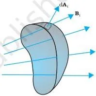
Flux changes when any one of the three letters in \(BA\cos\theta\) changes — B, A or \(\theta\) (NCERT, p. 5). Memory device: the three “knobs” of flux are B (changing field), A (stretching or shrinking the loop), and \(\theta\) (rotating the loop). Turn any knob and you induce an emf.
A steady field such as the earth’s produces no induced emf, because it does not change during the experiment (Example 6.2, NCERT p. 6). The earth’s own field is treated in our magnetism and matter notes.
Faraday’s Law: Induced EMF Equals the Rate of Change of Flux
Faraday’s law: the magnitude of the induced emf equals the time rate of change of magnetic flux through the circuit. Mathematically, \[ \varepsilon = -\frac{d\Phi_B}{dt} \qquad \text{(Eq. 6.3, NCERT p. 4)} \]
For a closely wound coil of \(N\) turns, each turn contributes equally, so (Eq. 6.4, NCERT p. 5):
\[ \varepsilon = -N\frac{d\Phi_B}{dt} \]
The negative sign carries the direction of the emf — that is Lenz’s law, the next section. In a closed circuit of resistance \(R\), the induced current is \(I = \varepsilon / R\).
The law is a rate, not a total: emf depends on how fast the flux changes, not on its size. That is why a fast push in Experiment 6.1 gave a larger deflection than a slow push.
Flux can be varied in three ways (NCERT, p. 5):
- Vary B — move a magnet or a current-carrying coil in or out (Experiments 6.1 and 6.2).
- Vary A — shrink or stretch the coil in a fixed field.
- Vary \(\theta\) — rotate the coil so the angle between \(\mathbf{B}\) and \(\mathbf{A}\) changes.
Lenz’s Law: Direction of the Induced Current — and the Energy Argument
Lenz’s law fixes the direction: the induced current opposes the change in magnetic flux that produced it (NCERT, p. 7). The minus sign in Faraday’s law is exactly this opposition.
Go back to Experiment 6.1 and read the two classic cases:
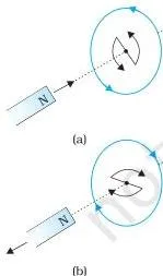
- N-pole approaching the coil: flux increases → induced current flows anticlockwise as seen from the magnet → the coil face acquires N-polarity → it repels the approaching magnet.
- N-pole receding from the coil: flux decreases → induced current flows clockwise → the coil face acquires S-polarity → it attracts the receding magnet.
Even an open circuit gets an emf across its ends — a closed path is needed for the current, not for the emf (NCERT, p. 7).
Four-step recipe for direction (works for any figure):
- Fix the direction of the existing magnetic field through the loop.
- Decide whether the flux is increasing or decreasing.
- Choose the induced field to oppose that change: opposite to the existing field if flux increases; in the same direction if flux decreases.
- Use the right-hand grip rule — thumb along the induced field, curved fingers give the direction of the induced current.
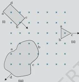
Apply the recipe to each loop of Fig 6.7 (NCERT, p. 8):
- Rectangular loop entering the field region: flux increases → current along bcdab.
- Triangular loop leaving the region: flux decreases → current along bacb.
- Irregular loop leaving the region: flux decreases → current along cdabc.
No current flows while a loop is completely inside or completely outside the field region (NCERT, p. 8).
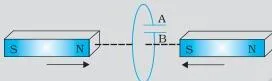
In the capacitor situation of Fig 6.9 (Example 6.5d, NCERT p. 9), plate A is at the higher potential.
Why Lenz’s law must be true — the energy argument. If the induced current aided the change, one gentle push on the magnet would accelerate it forever — a perpetual-motion machine. That violates conservation of energy, so it cannot happen. In the real case the magnet is repelled, the pusher does work, and that work appears as Joule heating (NCERT, p. 7).
Everyday devices run on Lenz’s law (extensions not in the textbook):
- Induction cooktops pass a rapidly changing current through a coil under the pan; the changing flux induces eddy currents in the metal pan, which heat the pan directly.
- Metal detectors use a coil whose changing field induces currents in hidden metal; the detector senses the metal’s response.
- Eddy current damping brings a moving coil in an instrument to rest quickly, because its induced currents oppose the motion.
In every case, the energy of the opposition ends up as heat — the same Joule heating of p. 7.
Motional EMF: Moving a Conductor in a Magnetic Field
When the induced emf comes from motion, it is called motional emf. There are two equivalent derivations (NCERT, pp. 9–10).
Derivation 1 — flux method: in the rectangular loop PQRS of Fig 6.10, the rod PQ of length \(l\) moves at speed \(v\). The flux enclosed is \(\Phi_B = Blx\). As \(x\) changes, \[ \varepsilon = -\frac{d\Phi_B}{dt} = -Bl\frac{dx}{dt} = Blv \qquad \text{(Eq. 6.5, NCERT p. 10)} \]
Derivation 2 — Lorentz force: each free charge \(q\) in the moving rod travels with speed \(v\) in the field, so it feels a force \(qvB\) directed towards Q. The work done per unit charge from P to Q is \(W/q = Blv\), identical to the flux result (NCERT, p. 10).
This is where the Lorentz force starts; revise it in our moving charges and magnetism notes.
The deep point: for a stationary conductor in a time-varying field, \(v = 0\), so the magnetic part of the Lorentz force vanishes: \(\mathbf{F} = q(\mathbf{E} + \mathbf{v}\times\mathbf{B}) = q\mathbf{E}\) (Eq. 6.6). The force must come from an induced electric field — a changing magnetic field generates an electric field (NCERT, p. 10).
Rotating rod (Example 6.6, NCERT p. 11): a point’s speed \(v = \omega r\) grows with distance from the axle, so integrate element by element, \(d\varepsilon = Bv\,dr = B\omega r\,dr\):
\[ \varepsilon = \int_0^R B\omega r\,dr = \frac{1}{2}B\omega R^2 \]
The same answer comes from the rate of change of the sector area (Method II of the example).
Wheel with 10 spokes (Example 6.7, NCERT p. 11): every spoke connects the same axle to the same rim, so the spoke emfs are in parallel — the number of spokes is immaterial; the wheel’s emf equals that of one spoke.
Condition to remember: \(\mathbf{B}\), the rod length \(l\), and the velocity \(\mathbf{v}\) must be mutually perpendicular. If \(\mathbf{v}\) is parallel to \(\mathbf{B}\), the rod cuts no flux lines and \(\varepsilon = 0\).
Inductance: Mutual and Self
In both kinds of induction, the flux through a coil is proportional to the current producing it: \(N\Phi_B \propto I\). The constant of proportionality is the inductance — a scalar with SI unit henry (H) and dimensions \([ML^2T^{-2}A^{-2}]\) (NCERT, p. 12).
Mutual inductance
Current in one coil sets up flux in a neighbouring coil (NCERT, pp. 12–14):
- Definition: \(N_1\Phi_1 = M_{12}I_2\) (Eq. 6.7).
- Two long coaxial solenoids: \(M_{12} = \mu_0 n_1 n_2 \pi r_1^2 l\) (Eq. 6.9), where \(n_1\), \(n_2\) are turns per unit length and \(r_1\) is the inner solenoid’s radius.
- Reciprocity: \(M_{12} = M_{21} = M\) (Eq. 6.12) — always true, and very useful when one direction is hard to compute.
- With a medium of relative permeability \(\mu_r\), multiply by \(\mu_r\).
- Induced emf: \(\varepsilon_1 = -M\frac{dI_2}{dt}\).
- Two concentric circular coils (Example 6.8, NCERT p. 14): \(M = \frac{\mu_0 \pi r_1^2}{2r_2}\) for \(r_1 \ll r_2\).
Self-inductance
A single coil opposes changes in its own current (NCERT, pp. 15–16):
- Definition: \(N\Phi_B = LI\) (Eq. 6.13).
- Back emf: \(\varepsilon = -L\frac{dI}{dt}\) (Eq. 6.14).
- Long solenoid: \(L = \mu_0 n^2 Al\) (Eq. 6.15); with a core of relative permeability \(\mu_r\), \(L = \mu_r\mu_0 n^2 Al\) (Eq. 6.16).
- The back emf opposes every change — increase or decrease — of current. \(L\) is the electromagnetic analogue of mass: electrical inertia (NCERT, p. 15).
Energy stored in an inductor
Work done against the back emf is stored as magnetic energy (NCERT, pp. 16–17):
\[ W = \frac{1}{2}LI^2 \qquad \text{(Eq. 6.17)} \]
\[ u_B = \frac{B^2}{2\mu_0} \qquad \text{(Eq. 6.18)} \]
Compare with electrostatic energy density \(u_E = \frac{1}{2}\varepsilon_0 E^2\): in both cases, energy is proportional to the square of the field strength (Example 6.9).
Mutual and self-inductance are easy to confuse in a hurry — the table fixes the differences.
| Feature | Mutual inductance \(M\) | Self-inductance \(L\) |
|---|---|---|
| Where the change happens | Current in one coil induces emf in another nearby coil | Current change in the same coil induces emf in itself |
| Defining equation | \(N_1\Phi_1 = M I_2\) | \(N\Phi_B = L I\) |
| Induced emf | \(\varepsilon_1 = -M\frac{dI_2}{dt}\) | \(\varepsilon = -L\frac{dI}{dt}\) |
| SI unit | henry (H) | henry (H) |
| Depends on | Geometry of both coils, their separation and orientation, and the medium | Geometry of the single coil and the medium |
| Standard example | Two long coaxial solenoids: \(M = \mu_0 n_1 n_2 \pi r_1^2 l\) | Long solenoid: \(L = \mu_r\mu_0 n^2 Al\) |
The AC Generator: How a Rotating Coil Produces Alternating EMF
An AC generator converts mechanical energy into electrical energy by rotating a coil in a magnetic field (NCERT, p. 18). Rotation changes the angle \(\theta\), which changes the flux.
With constant angular speed \(\omega\), the angle at time \(t\) is \(\theta = \omega t\), so \(\Phi_B = BA\cos\omega t\). Faraday’s law gives (Eq. 6.19, NCERT p. 18):
\[ \varepsilon = -N\frac{d\Phi_B}{dt} = NBA\omega\sin\omega t \]
The peak value is \(\varepsilon_0 = NBA\omega = NBA(2\pi\nu)\) (Eqs. 6.20–6.21), where \(\nu\) is the frequency of rotation in Hz.
Why sinusoidal? The emf is largest when the flux changes fastest — at \(\theta = 90^\circ\) and \(270^\circ\) — and zero when the flux is momentarily a maximum or minimum (Fig 6.14, NCERT p. 19). Because \(\sin\omega t\) swings between +1 and −1, the polarity reverses periodically: that reversal is exactly what makes the current alternating.
The working parts (Fig 6.13, NCERT pp. 17–18): the armature coil is mounted on a rotor shaft and rotated in the magnetic field; the coil ends are connected to the external circuit through slip rings and brushes.
- Energy conversion: mechanical (rotation) → electrical.
- Commercial generators are hydro, thermal or nuclear, depending on what drives the turbine.
- In many large machines the coil is stationary and the electromagnets rotate.
- The grid frequency in India is 50 Hz (NCERT, p. 19).
What an alternating emf does in a circuit is the subject of the next chapter — our alternating current notes pick up from exactly this equation.
Definitions at a Glance
Every term the chapter introduces, in one table.
| Term | Meaning | Equation / example |
|---|---|---|
| Electromagnetic induction | Generation of electric current by a changing magnetic flux; demonstrated by Faraday and Henry around 1830 (NCERT, p. 1) | Experiments 6.1–6.3 |
| Magnetic flux \(\Phi_B\) | Scalar measure of magnetic field passing through a surface; unit Wb | \(\Phi_B = BA\cos\theta\) |
| Flux linkage \(N\Phi_B\) | Flux summed over all N turns of a closely wound coil | \(N\Phi_B = LI\) |
| Induced emf | Work done per unit charge by a changing flux; unit V | \(\varepsilon = -N\frac{d\Phi_B}{dt}\) |
| Motional emf | emf from a conductor cutting field lines | \(\varepsilon = Blv\) |
| Mutual inductance \(M\) | Flux linkage in one coil per unit current in another; unit H | \(\varepsilon_1 = -M\frac{dI_2}{dt}\) |
| Self-inductance \(L\) | Flux linkage per unit current in the same coil; unit H | \(\varepsilon = -L\frac{dI}{dt}\) |
| Back emf | Self-induced emf opposing any change in current | Opposes growth and decay of \(I\) |
| Alternating current | Current whose direction reverses periodically, as produced by an AC generator | \(\varepsilon = \varepsilon_0\sin\omega t\) |
Formula Sheet: Symbols, Units and When Each Equation Applies
Two tables: the SI quantities, then every equation with its conditions.
Key quantities (NCERT, p. 21)
| Quantity | Symbol | SI unit | Dimensions |
|---|---|---|---|
| Magnetic flux | \(\Phi_B\) | Wb (weber) | \([ML^2T^{-2}A^{-1}]\) |
| EMF | \(\varepsilon\) | V (volt) | \([ML^2T^{-3}A^{-1}]\) |
| Mutual inductance | \(M\) | H (henry) | \([ML^2T^{-2}A^{-2}]\) |
| Self-inductance | \(L\) | H (henry) | \([ML^2T^{-2}A^{-2}]\) |
Equations: symbols and when to use them
| Formula | Symbols and units | When to use |
|---|---|---|
| \(\Phi_B = BA\cos\theta\) | \(\theta\) = angle between \(\mathbf{B}\) and area vector \(\mathbf{A}\); Wb | Flux through a plane area in a uniform field |
| \(\Phi_B = \sum B_i \cdot dA_i\) | Sum over area elements of the surface | Non-uniform field or curved surface |
| \(\varepsilon = -N\frac{d\Phi_B}{dt}\) | \(N\) = number of turns; V | Faraday’s law for a coil (closed circuit: \(I = \varepsilon/R\)) |
| \(\varepsilon = Blv\) | \(l\) = conductor length, \(v\) = speed \(\perp \mathbf{B}\); V | Rod sliding on rails — motional emf |
| \(\varepsilon = \frac{1}{2}B\omega R^2\) | \(R\) = rod length, \(\omega\) = angular speed; V | Rod rotating about one end |
| \(\varepsilon_1 = -M\frac{dI_2}{dt}\) | \(M\) = mutual inductance; H, V | Changing current in one coil, emf in another |
| \(M = \mu_0 n_1 n_2 \pi r_1^2 l\) | \(n\) = turns per unit length, \(r_1\) = inner radius, \(l\) = length | Two long coaxial solenoids |
| \(L = \mu_r\mu_0 n^2 Al\) | \(A\) = cross-section area, \(\mu_r\) = relative permeability; H | Self-inductance of a long solenoid |
| \(\varepsilon = -L\frac{dI}{dt}\) | \(L\) = self-inductance; H, V | Back emf in a single coil |
| \(W = \frac{1}{2}LI^2\) | \(I\) = current; J | Energy stored in an inductor |
| \(u_B = \frac{B^2}{2\mu_0}\) | \(B\) = field strength; J/m³ | Magnetic energy density |
| \(\varepsilon = NBA\omega\sin\omega t\) with \(\varepsilon_0 = NBA(2\pi\nu)\) | \(\nu\) = frequency; Hz, V | AC generator output |
Worked Examples: Solving Numerical Problems Step by Step
Worked Example 1: Faraday’s law — a coil whose field is switched off
Method: compute the flux change per turn, multiply by the number of turns, divide by the time interval.
Given: \(N = 250\), radius \(r = 4.0\ \text{cm} = 0.040\ \text{m}\), \(R = 8.0\ \Omega\), \(B_i = 0.30\ \text{T}\), \(B_f = 0\), \(\Delta t = 0.15\ \text{s}\).
The plane is perpendicular to the field, so \(\theta = 0^\circ\).
- Step 1: Area of the coil: \(A = \pi r^2 = \pi(0.040)^2 \approx 5.0 \times 10^{-3}\ \text{m}^2\).
- Step 2: Initial flux per turn: \(\Phi_i = BA\cos 0^\circ = 0.30 \times 5.0 \times 10^{-3} = 1.5 \times 10^{-3}\ \text{Wb}\).
- Step 3: Final flux is zero, so \(|\Delta\Phi| = 1.5 \times 10^{-3}\ \text{Wb}\) per turn.
- Step 4: Magnitude of the induced emf:
\[ |\varepsilon| = N\frac{|\Delta\Phi|}{\Delta t} = 250 \times \frac{1.5 \times 10^{-3}}{0.15} = 2.5\ \text{V} \]
Step 5: Current in the closed coil: \(I = \varepsilon/R = 2.5/8.0 \approx 0.31\ \text{A}\).
Final answer: \(\varepsilon \approx 2.5\ \text{V}\), \(I \approx 0.31\ \text{A}\). The units V and A confirm that flux was taken in weber and time in seconds.
Worked Example 2: Motional emf — a rod sliding on rails
Method: \(\varepsilon = Blv\), valid because the rod is perpendicular to both the field and its velocity.
Given: \(l = 0.60\ \text{m}\), \(v = 2.0\ \text{m/s}\), \(B = 0.50\ \text{T}\), loop resistance \(R = 3.0\ \Omega\).
- Step 1: \(\varepsilon = Blv = 0.50 \times 0.60 \times 2.0 = 0.60\ \text{V}\).
- Step 2: \(I = \varepsilon/R = 0.60/3.0 = 0.20\ \text{A}\).
Step 3 (direction): the rod’s motion increases the loop area and hence the flux; by Lenz’s law the induced current must oppose that increase, so it flows to produce a field opposing the original one.
Final answer: \(\varepsilon = 0.60\ \text{V}\), \(I = 0.20\ \text{A}\). Lenz’s law fixes the direction; the magnitude follows from Faraday’s law in the motional form \(\varepsilon = Blv\).
Worked Example 3: Rotating rod — emf between the centre and the rim
Method: integrate \(d\varepsilon = Bv\,dr = B\omega r\,dr\) from the axle to the tip.
Given: \(R = 0.50\ \text{m}\), \(\nu = 40\ \text{rev/s}\), \(B = 0.80\ \text{T}\).
- Step 1: \(\omega = 2\pi\nu = 2\pi \times 40 \approx 251\ \text{rad/s}\).
- Step 2: integrate:
\[ \varepsilon = \int_0^R B\omega r\,dr = \frac{1}{2}B\omega R^2 = \frac{1}{2} \times 0.80 \times 251 \times (0.50)^2 \approx 25\ \text{V} \]
Final answer: \(\varepsilon \approx 25\ \text{V}\) between centre and rim. The factor \(1/2\) appears because speed \(v = \omega r\) grows linearly from zero at the axle to \(\omega R\) at the tip.
Worked Example 4: AC generator — peak emf of a rotating coil
Method: use \(\varepsilon_0 = NBA\omega = NBA(2\pi\nu)\), the peak value of \(\varepsilon = NBA\omega\sin\omega t\).
Given: \(N = 200\), \(A = 0.050\ \text{m}^2\), \(\nu = 25\ \text{rev/s}\), \(B = 0.020\ \text{T}\).
- Step 1: \(\omega = 2\pi \times 25 \approx 157\ \text{rad/s}\).
- Step 2: \(\varepsilon_0 = NBA\omega = 200 \times 0.020 \times 0.050 \times 157 \approx 31\ \text{V}\).
Final answer: peak emf \(\varepsilon_0 \approx 31\ \text{V}\). The instantaneous emf swings between \(+31\ \text{V}\) and \(-31\ \text{V}\) at frequency \(\nu = 25\ \text{Hz}\).
Common Mistakes Students Make in Electromagnetic Induction
Six mark-losing slips, each with the rule that fixes it.
| Students write… | Correct rule | How to check your answer |
|---|---|---|
| \(\varepsilon = BAv\) for a moving rod | \(\varepsilon = Blv\) — \(l\) is the conductor length, and \(v\) must be perpendicular to \(B\). If \(v \parallel B\), no flux is cut and \(\varepsilon = 0\) (NCERT, p. 10). | Check units: \(\text{T} \times \text{m} \times \text{m/s} = \text{V}\). Area \(A\) never appears in motional emf. |
| \(\Phi_B = BA\) in every situation | \(\Phi_B = BA\cos\theta\). A loop whose plane is parallel to the field (\(\theta = 90^\circ\)) has zero flux (NCERT, p. 4). | Ask: what is the angle between the area vector and the field? If unsure, draw it. |
| \(\varepsilon = -\frac{d\Phi_B}{dt}\) for a coil | \(\varepsilon = -N\frac{d\Phi_B}{dt}\) — each of the \(N\) turns contributes; flux linkage is \(N\Phi_B\), not \(\Phi_B\) (NCERT, p. 5). | Count the turns in the question. If \(N\) is given, it multiplies the emf. |
| Reading the minus sign as a smaller emf | Compute the magnitude \(|\varepsilon| = N|\Delta\Phi|/\Delta t\) first; find the direction separately with Lenz’s law (NCERT, pp. 5, 7). | The minus sign gives polarity, not size. Write both parts in the answer. |
| A very strong stationary magnet induces current in a stationary coil | No — induction needs a changing flux, not a strong field. Either the magnet or the coil must move (Example 6.5a, NCERT p. 9). | Ask: is the flux through the loop changing with time? |
| Adding the emfs of all spokes of a rotating wheel | The wheel’s emf equals that of one spoke, because all spokes are effectively in parallel (Example 6.7, NCERT p. 11). | Every spoke touches the same axle and the same rim — two common terminals mean parallel. |
Keep unit discipline in every numerical: flux in Wb (T m²), emf in V, inductance in H.
Exam Notes: Where the Marks Are
Observed patterns — the steps examiners consistently reward. No question is guaranteed, but this is where the weight sits.
- State Lenz’s law fully, then add the one-sentence energy argument. The reasoning — an aiding current would mean perpetual motion, so the induced current must oppose the change and the work done appears as Joule heating — earns the concept marks (NCERT, p. 7).
- Derive \(\varepsilon = Blv\) both ways: the flux method (rate of change of area) and the Lorentz-force method on the charges. Naming the condition that \(B\), \(l\), \(v\) are mutually perpendicular is part of the answer (NCERT, p. 10).
- Derive the solenoid results from flux linkage: \(L = \mu_0 n^2 Al\) for self-inductance (p. 16) and \(M = \mu_0 n_1 n_2 \pi r_1^2 l\) for coaxial solenoids (p. 13). Quoting reciprocity \(M_{12} = M_{21}\) completes the answer (p. 14).
- Write the energy results side by side: \(W = \frac{1}{2}LI^2\), \(u_B = B^2/2\mu_0\), and the comparison \(u_E = \frac{1}{2}\varepsilon_0 E^2\) — energy proportional to field strength squared (pp. 16–17).
- Quote the two standard rotating-conductor results: \(\varepsilon = \frac{1}{2}B\omega R^2\) and “the spoke emfs are in parallel” (p. 11).
- Derive the AC generator emf end to end: from \(\Phi_B = BA\cos\omega t\) to \(\varepsilon = NBA\omega\sin\omega t\), identifying the peak \(\varepsilon_0 = NBA(2\pi\nu)\) and the 50 Hz grid frequency (pp. 18–19).
- Units carry marks. Write Wb for flux, V for emf and H for inductance in final answers (p. 21).
The chapter-end exercises (6.1–6.8, NCERT pp. 21–23) fall into two groups: direction-prediction through Lenz’s law (6.1–6.2), and numericals on solenoid flux, motional emf, the rotating rod, a falling wire, self-inductance and mutual inductance (6.3–6.8). In numericals, setting up the flux/emf equations carries the marks; the arithmetic is simple.
10-Minute Revision Recap
The whole chapter on one scannable table.
| Concept | Equation or rule | One-line meaning |
|---|---|---|
| Magnetic flux | \(\Phi_B = BA\cos\theta\), unit Wb | Scalar measure of field lines through a loop |
| Faraday’s law | \(\varepsilon = -N\frac{d\Phi_B}{dt}\) | emf equals the rate of change of flux linkage |
| Lenz’s law | induced current opposes the flux change | Gives the minus sign; enforces energy conservation |
| Motional emf | \(\varepsilon = Blv\); rotating rod \(\varepsilon = \frac{1}{2}B\omega R^2\) | Moving a conductor cuts field lines and drives charges |
| Mutual inductance | \(\varepsilon_1 = -M\frac{dI_2}{dt}\); \(M = \mu_0 n_1 n_2 \pi r_1^2 l\) | Changing current in one coil induces emf in another |
| Self-inductance | \(\varepsilon = -L\frac{dI}{dt}\); \(L = \mu_r\mu_0 n^2 Al\) | The coil opposes any change in its own current |
| Energy stored | \(W = \frac{1}{2}LI^2\); \(u_B = \frac{B^2}{2\mu_0}\) | Inductors store magnetic energy like mass stores kinetic energy |
| AC generator | \(\varepsilon = NBA\omega\sin\omega t\), \(\varepsilon_0 = NBA\omega\) | Converts mechanical energy into alternating emf |
One closing idea from the chapter (NCERT, p. 21): motional emf is fully explained by the Lorentz force on moving charges, but a stationary conductor in a time-varying field needs an induced electric field — a hint that Faraday’s law is connected to relativity. Revising the full syllabus?
The class 12 notes index collects every chapter, and the CBSE notes library covers all subjects and classes.
FAQs on Electromagnetic Induction
What is the difference between magnetic flux and flux linkage?
Flux \(\Phi_B\) is the field through one turn of the coil. Flux linkage is \(N\Phi_B\) — the flux of all \(N\) turns added together (NCERT, p. 12). Faraday’s law for a coil is written with the linkage: \(\varepsilon = -N\frac{d\Phi_B}{dt}\).
Why does Lenz’s law obey conservation of energy?
If the induced current aided the change, one gentle push would accelerate the magnet forever — a perpetual-motion machine. Instead, the induced current opposes the change, so you must do work, and that work appears as Joule heating (NCERT, p. 7).
Can a strong stationary magnet induce a current in a stationary coil?
No. Induction needs a changing flux, not a strong field. A stationary magnet in a stationary coil gives zero flux change, however strong the magnet is (Example 6.5a, NCERT p. 9).
When is motional emf zero even if a conductor moves in a magnetic field?
When \(\mathbf{v}\) is parallel to \(\mathbf{B}\), or the rod itself is parallel to \(\mathbf{B}\). The condition for \(\varepsilon = Blv\) is that \(B\), \(l\) and \(v\) are mutually perpendicular (NCERT, p. 10).
Why is the number of spokes immaterial in the rotating-wheel emf problem?
Every spoke connects the same axle to the same rim, so all spoke emfs are in parallel. The wheel’s emf equals that of a single spoke (Example 6.7, NCERT p. 11).
Why is self-inductance called electrical inertia?
Because \(L\) opposes any change in current just as mass opposes any change in velocity — and both act as inertia in an energy expression: \(\frac{1}{2}LI^2\) mirrors \(\frac{1}{2}mv^2\) (NCERT, p. 15).
Reference: NCERT Class 12 Physics textbook, chapter Electromagnetic Induction.
Explore Class 12 Physics Notes
More for this chapter:
Class 12 Physics on LearnCBSE:
Related chapters: